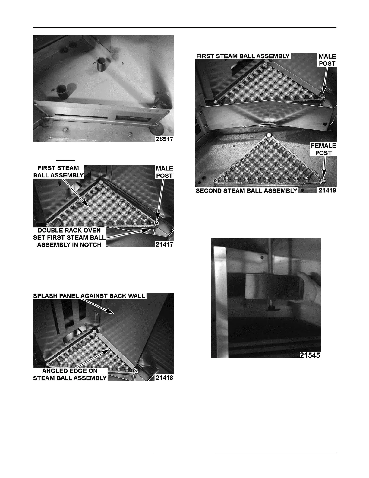
Fig. 59
NOTE: Fig. 59 shows Single Rack Oven.
Fig. 60
4.
(Only on ovens with 38 castings) Install splash
panel with angled ledge on top of first steam ball
assembly and the baffle supported by the back
wall .
Fig. 61
5.
The next steam ball assembly must be put in
place matching the female post with male post of
previous assembly (total of 30 or 38 sections for
OV500G2-EE & OV500E2 ovens, total of 15
sections for OV500E1, and total of 20 sections
for OV500G1-EE ovens to install).
NOTE:
The assemblies will not set level if the sections
are not oriented correctly.
Fig. 62
6. Before last couple sets of assemblies are
installed, slide spray guard onto manifold. Align
manifold with steam ball assemblies. Allow spray
guard to hang on manifold.
Fig. 63
7.
After all assemblies are installed, place spray
guard on last set of steam balls & install water
guides to edge of assemblies.
8. Begin with the top assembly and install water
guides over front rim of the top, then every other
assembly (total of 7 water guides for all ovens.
INSTALLATION INSTRUCTIONS OV500-EE SERIES GAS RACK OVENS AND OV500 SERIES ELECTRIC RACK
OVENS - INSTALLING OVEN
F45469 Rev. D (1019) Page 30 of 49