Example 9 Power not on
Analysis and troubleshooting: Step 1: check power supply of power board and find that power has
no voltage output, unplug flat cable on power board and there is still no voltage output on power board,
so we can confirm that trouble lies in power board.
Step 2: observe element on power board and find that U505 (KAIM0880) is burnt down, then check
fuse and find that fuse has been burnt down.
Step 3: use multimeter to test bridge circuit BD501 and find no abnormality (pay attention to the pin
sequence of BD501).
Step 4: change fuse and U505 (KAIM0880), and trouble is removed.
Conclusion: when servicing power board, if you find that fuse and switch module have been burnt
down, please check whether diode on bridge circuit has been burnt down.
Example 10 Power amplifier has no sound
Analysis and troubleshooting: Step 1: check HDET signal of pin 24 of XS207 on power amplifier
board and it is +3.3V, voltage on XP101 and +28.5V voltage on XP503 are both normal.
Step 2: check SDATA0, SDATA1, SDATA2 (R294, R295, R296) output on decode board and it is
normal.
Step 3: check SDACSW (R98), SDASLSR (R100), SDALR (R101) signals on power amplifier board
and they are all normal.
Step 4: check each output pin of TAS5508 and they al have no output.
Step 5: check TAS5508 power supply and MUTE signal and they are both normal.
Step 6: check pin 63 MCLK of TAS5508 and it is about 3MHZ, pin 26 LRCK is 48KHZ, pin 27 SCLK
is about 12.3MHZ, the external crystal oscillation clock of chip is about 13.5MHZ, which are all normal.
Step 7: after changing TAS5508, power amplifier still has no sound output.
Step 8: after changing N13 (TAS5112), output is normal.
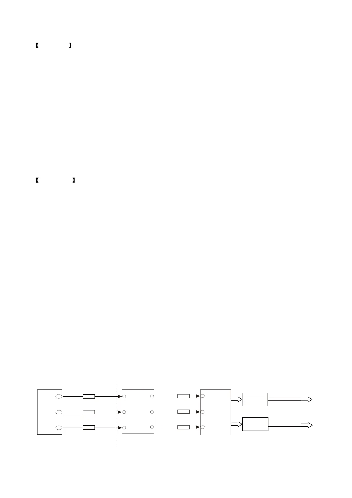
Conclusion: each input signal, power supply and clock signal of N12 (TAS5508 ) are all normal but
there is no output, so directly change N12; but trouble is still not removed after changing, so the rear
stage circuit may probably cause that N12 has no output, after changing N13, it resumes normal; the
internal trouble of N13 leads to the shotr circuit of N12 output pin, N12 is with self-protection function to
stop outputting signal. Power amplifier board audio signal flow chart is shown in the figure 3.3.1.4:
156
ASDAT2
R296
SDATA2
11
12
Decode board
SDA CSW
R98
28
N14
TAS5112
Power amplifier board
MT1389
154
155
ASDAT0
ASDAT1
R294
R295
SDAT A0
SDATA1
N3
74HCT125
5
9
8
6
SDA LR
SDA SLSR
R101
R100
30
31
N12
TAS5508
N13
TAS51 12
Surround L/R channel
and subwoofer channel
output
Front L/R channel and
centre channel output
Figure 3.3.1.4 Audio signal flow chart
- 34 -