Headphone
socket
HDET
XS106
6
HDET
XS106
6 6
HDET
7 7
HDET
XP204
7 7
HDET
XP201
27
Power
amplifier board
XS207
Decode
board
XS207
27
181
U201
MT1389
4094DAT
24
Decode
board
XS207
PH_SEL
XS207
Power
amplifier board
6 27
27
96
24 24 24
N12
TAS5508
12
Figure 3.3.1.3 HDET signal flow chart
Example 8 Power not on
Analysis and troubleshooting: Step 1: check each circuit power supply of power board and it is
normal.
Step 2: check clock circuit and it is normal (frequency is 27MHZ, VPP=1.8V, DC voltage on two
ends is 0.75V), during the course of checking machine, you may directly test on two ends of R244 and
R248, thus it is convenient, but the machine will be down or give whistle sound during test, but the test
result will not be affected basically, if the influence is obvious when testing on one end of resistor, you
may test the other end. Of course, as for the defective machine that power not on, the above
phenomenon will not be noticed.
Step 3: check reset circuit and voltage is 3.3V, which is normal; reset by force (use a lead to make
pin 6 of U205 (HCU04) grounding for about one second), nut power is still not on, so we can preliminarily
decide that it has nothing to do with reset circuit.
Step 4: check power supply of MT1389 according to the troubleshooting process and it is normal;
check power supply of U214 (FLASH), U211 (SDRAM) and it is normal; check pin 5 and pin 6 of I2C
(U202) and they are both at +2.5V, which is also normal.
Step 5: after changing FLASH, trouble is removed.
Conclusion if there is oscillograph, firstly check whether pin 29 of FLASH has waveform, if not, a
trouble may exist between MT1389 and FLASH. If there is no oscillograph, firstly consider changing
FLASH, then changing SDRAM, if trouble is still not removed, then consider changing MT1389.
HDET_IN
HDET_IN
HDET_OUT
Test the resistance to ground of HDET signal of pin 7 of XS207 and it is 0 ohm, and it should be infinite
in normal conditions, so we preliminarily confirm that HDET signal is short-circuited to ground, unplug
flat cable on XS201, test the resistance to ground of pin 7 of XS201 and it is infinite, which is normal, and
now test the resistance to ground of pin 7 (HDET) of XP204 on panel and it is still 0 ohm, so we can
consider that problem lies in main panel, headphone board or flat cable, unplug the flat cable between
panel and headphone, test the resistance to ground of pin 7 of XP204 on panel and it is infinite, so we
can confirm that problem lies in headphone board, but joint welding has not been found in headphone
board, so only socket has trouble, after changing headphone socket, trouble is removed.
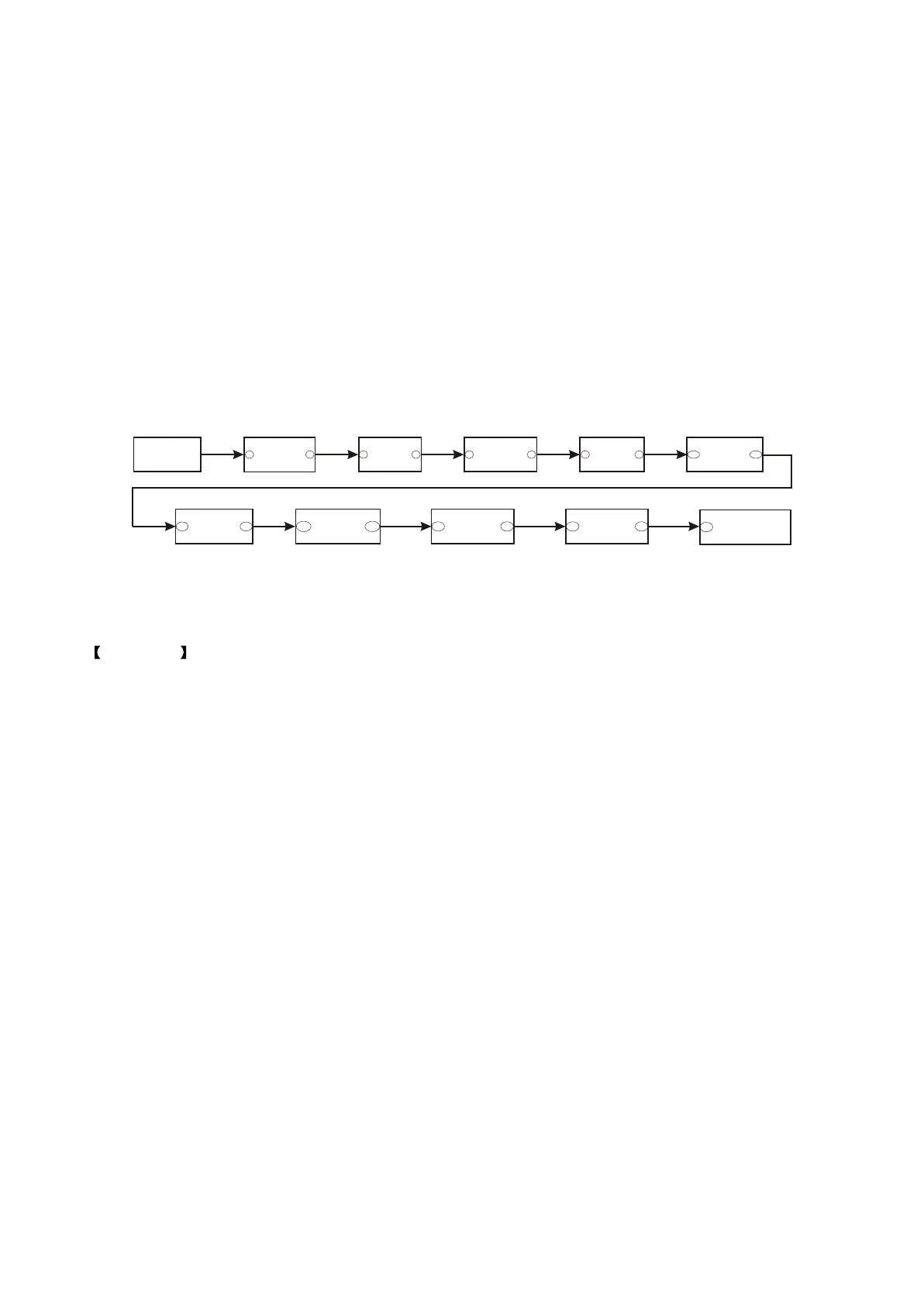
Conclusion: that the spring plate inside headphone socket has trouble makes HDET signal and
ground connected together, HDET signal flow is shown in the figure 3.3.1.3:
- 33 -