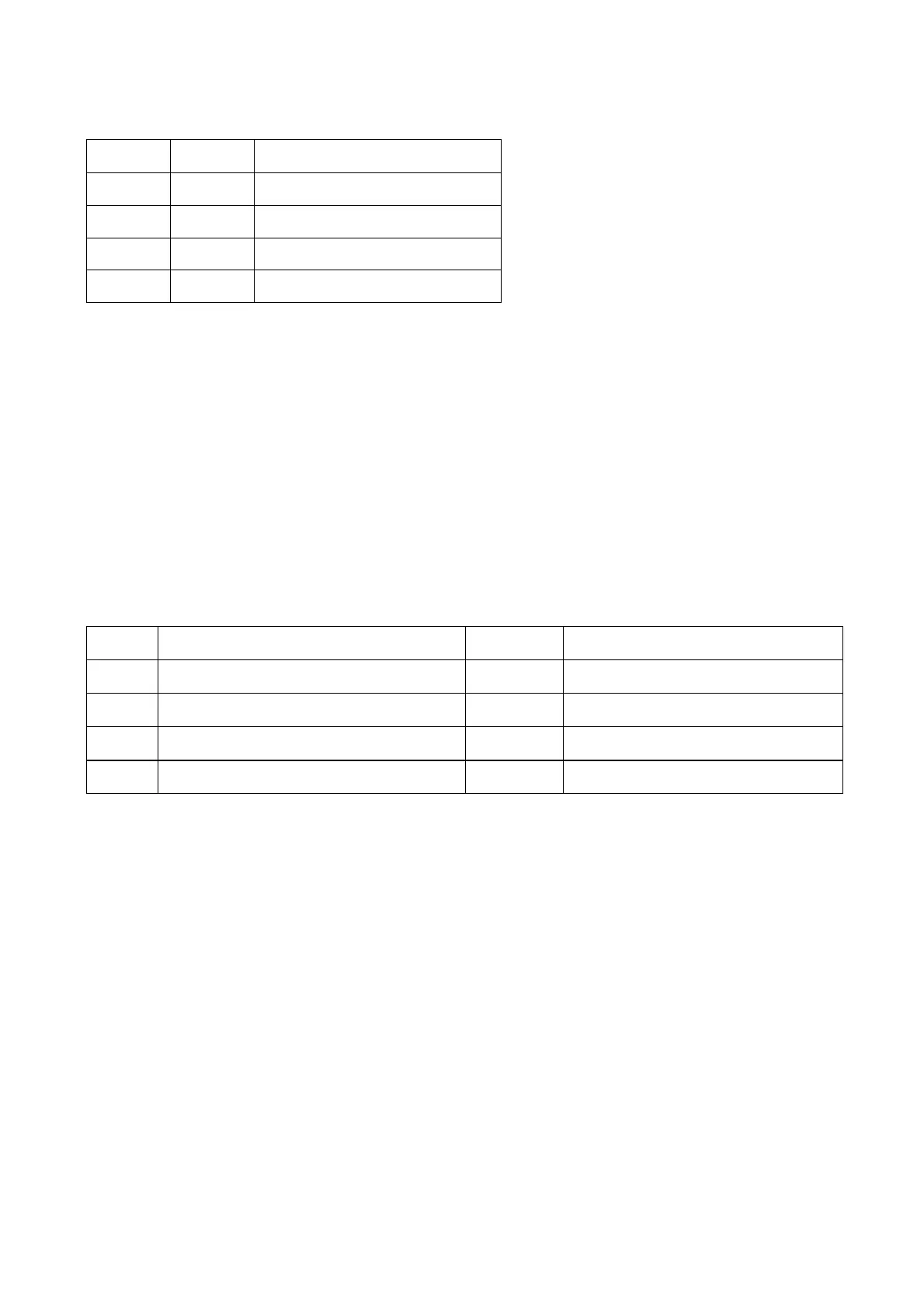
5. Table 3 is shown as follows:
SD RESET Function description
0 0 none
0 1 Device in protection mode
1 0 Device set in high impedance state
1 1 normal working
3.5.14 Function introduction to 5L0380
Pin 3 of 5L0380 is controlled by feedback pin 4 to make it on for a while and off for another while to form
pulse DC to control coupling quantity of transformer. When secondary output voltage of transformer is on the
high side, under the control of pin 4, disconnection time of pin 3 gets longer and coupling quantity of
transformer decreases to make output voltage get lower gradually; when secondary output voltage of
transformer is on the low side, disconnection time of pin 3 gets shorter, connection time gets longer (connect
inside 5L0380), coupling quantity of transformer decreases and secondary output voltage gets larger
gradually. Pin function is shown as the following table:
Pin Function Voltage Remark
1 Grounding 0
2 Voltage supply 16V supply voltage for 5L0380 after starting up
3 310V power supply input 310V
4 Control of space occupation ratio to pulse width
3.5.15 function introduction to LM431A
U503 (LM431A) is a 2.5V comparator, shown as the figure 3.5.15.1. Compared the inputted voltage of R
end with 2.5V, when voltage of R end is more than 2.5V, KA end is on and photoelectric coupler starts to send
out photocurrent; when voltage of R end is less than 2.5V, KA end is cutoff and photoelectric coupler does
not send out photocurrent. CPU+3.3V in power board circuit must be kept in 3.3V, for the function of
comparator. No matter more than or less than 3.3V, through on and off status of comparator, it will control the
on state of the output end of photoelectric coupler LM431A to adjust the output space occupation ratio of
switch module to control the output voltage of transformer and masthead the power supply of the whole
system.
- 93 -