Home
Beckhoff
Touch terminals
EL10 Series
Beckhoff EL10 Series User Manual
4
of 1
of 1 rating
106 pages
Give review
Manual
Specs
To Next Page
To Next Page
To Previous Page
To Previous Page
Loading...
Appendix
EL10xx, EL11xx
101
Version: 4.5
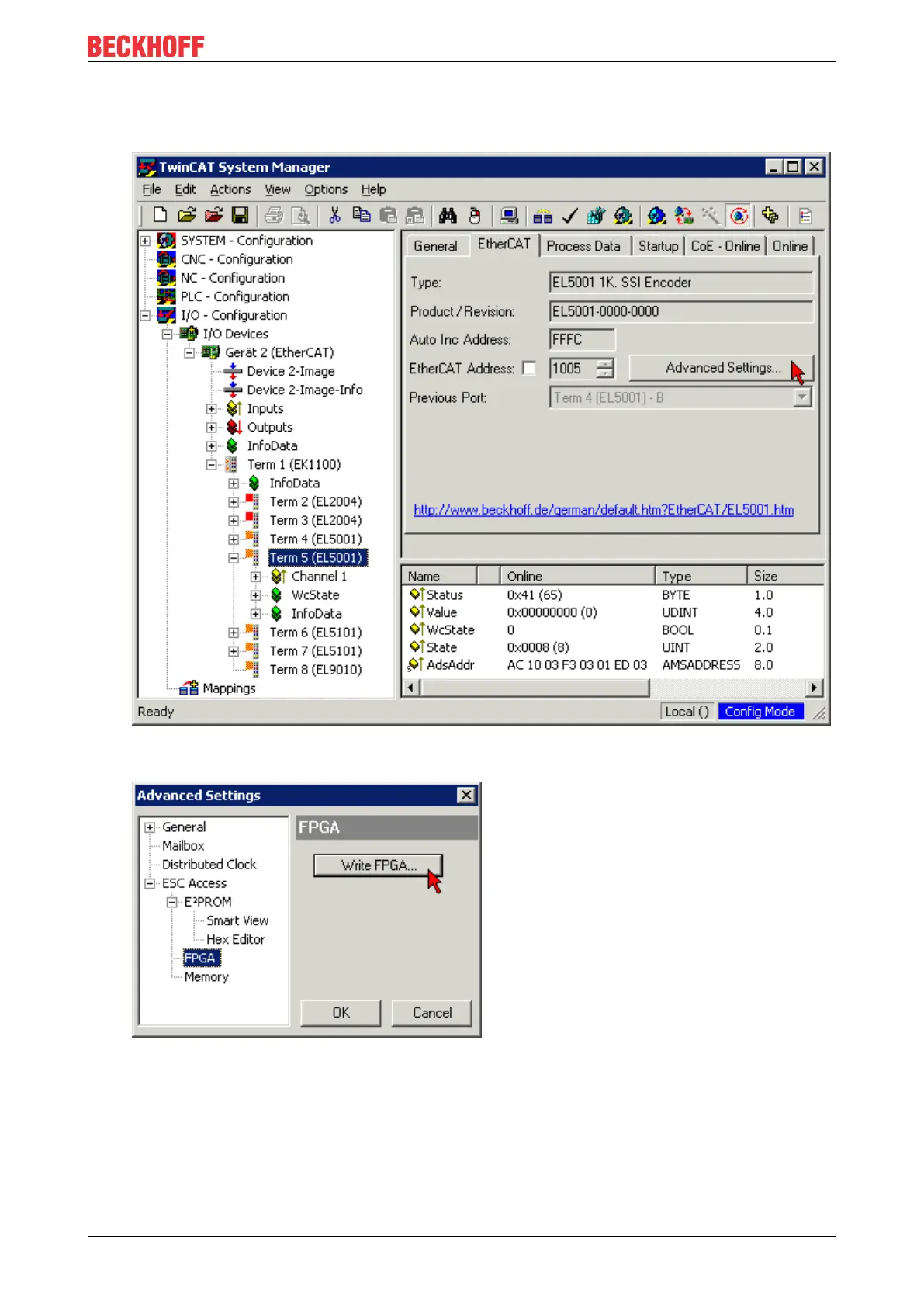
•
In the TwinCAT System Manager select the terminal for which the FPGA firmware is to be updated (in
the example: Terminal 5: EL5001) and
click the
Advanced Settings
button in the
EtherCAT
tab:
•
The
Advanced Settings
dialog appears. Under
ESC Access/E²PROM
/FPGA click on
Write FPGA
button:
100
102
Table of Contents
Table of Contents
3
1 Foreword
5
Product Overview Ethercat Digital Input Terminals
5
Notes on the Documentation
5
Safety Instructions
7
Documentation Issue Status
8
Version Identification of Ethercat Devices
9
Fig. 1 EL5021 el Terminal, Standard IP20 IO Device with Serial/ Batch Number and Revision ID (Since 2014/01)
10
Fig. 2 EK1100 Ethercat Coupler, Standard IP20 IO Device with Serial/ Batch Number
11
Fig. 3 CU2016 Switch with Serial/ Batch Number
11
Fig. 4 EL3202-0020 with Serial/ Batch Number 26131006 and Unique ID-Number 204418
11
Fig. 5 EP1258-00001 IP67 Ethercat Box with Batch Number/ Date Code 22090101 and Unique Se- Rial Number 158102
12
Fig. 6 EP1908-0002 IP67 Ethercat Safety Box with Batch Number/ Date Code 071201FF and Unique Serial Number 00346070
12
Fig. 7 EL2904 IP20 Safety Terminal with Batch Number/ Date Code 50110302 and Unique Serial Num- Ber 00331701
12
Fig. 8 ELM3604-0002 Terminal with Unique ID Number (QR Code) 100001051 and Serial/ Batch Num- Ber 44160201
12
Beckhoff Identification Code (BIC)
13
Fig. 9 BIC as Data Matrix Code (DMC, Code Scheme ECC200)
13
2 Product Overview
15
EL1002, EL1004-00X0, EL1008 - Introduction
15
EL1002 - Leds and Connection
15
Fig. 10 EL1002
15
EL1004-00X0 - Leds and Connection
16
Fig. 11 EL1004
16
EL1008 - Leds and Connection
17
Fig. 12 EL1008
17
EL1002, EL1004-00X0, EL1008 - Technical Data
18
EL1012, EL1014, EL1018 - Introduction
19
EL1012 - Leds and Connection
19
Fig. 13 EL1012
19
EL1014 - Leds and Connection
20
Fig. 14 EL1014
20
EL1018 - Leds and Connection
21
Fig. 15 EL1018
21
EL1012, EL1014, EL1018 - Technical Data
22
EL1024, EL1034 - Introduction
23
EL1024 - Leds and Connection
23
EL1034 - Leds and Connection
24
Fig. 17 EL1034
24
EL1024, EL1034 - Technical Data
25
Fig. 16 EL1024
25
El108X, El109X - Introduction
26
EL1084, EL1094 - Leds and Connection
26
Fig. 18 EL1084, EL1094
26
EL1088, EL1098 - Leds and Connection
27
Fig. 19 EL1088, EL1098
27
EL1084, EL1088, EL1094, EL1098 - Technical Data
28
EL1104, EL1114 - Introduction
29
EL1104, EL1114 - Leds and Connection
29
Fig. 20 EL1104
29
EL1104, EL1114 - Technical Data
30
EL1124, EL1144, EL1134 - Introduction
31
EL1124, EL1144, EL1134 - Leds and Connection
31
Fig. 21 EL1124
31
EL1124, EL1144, EL1134 - Technical Data
32
Application Notes
33
3 Basics Communication
34
Ethercat Basics
34
Ethercat Cabling - Wire-Bound
34
General Notes for Setting the Watchdog
35
Fig. 22 System Manager Current Calculation
35
Fig. 23 Ethercat Tab -> Advanced Settings -> Behavior -> Watchdog
36
Ethercat State Machine
37
Fig. 24 States of the Ethercat State Machine
38
Coe - Interface: Notes
39
Distributed Clock
40
4 Mounting and Wiring
41
Instructions for ESD Protection
41
Installation on Mounting Rails
41
Fig. 25 Spring Contacts of the Beckhoff I/O Components
41
Fig. 26 Attaching on Mounting Rail
42
Fig. 27 Disassembling of Terminal
43
Installation Positions
44
Fig. 28 Power Contact on Left Side
44
Fig. 29 Recommended Distances for Standard Installation Position
45
Installation Instructions for Enhanced Mechanical Load Capacity
46
Fig. 30 Other Installation Positions
46
Positioning of Passive Terminals
47
Connection
47
Connection System
47
Fig. 31 Correct Positioning
47
Fig. 32 Incorrect Positioning
47
Fig. 33 Standard Wiring
48
Fig. 34 Pluggable Wiring
48
Fig. 35 High Density Terminals
49
Wiring
50
Fig. 36 Connecting a Cable on a Terminal Point
50
Shielding
51
ATEX - Special Conditions (Standard Temperature Range)
51
ATEX - Special Conditions (Extended Temperature Range)
52
ATEX Documentation
53
UL Notice
53
5 Commissioning
54
Twincat Development Environment
54
Installation of the Twincat Real-Time Driver
54
Fig. 37 System Manager "Options" (Twincat 2)
55
Fig. 38 Call up under VS Shell (Twincat 3)
55
Fig. 39 Overview of Network Interfaces
55
Fig. 40 Ethercat Device Properties(Twincat 2): Click on „Compatible Devices
56
Fig. 41 Windows Properties of the Network Interface
56
Notes Regarding ESI Device Description
60
OFFLINE Configuration Creation
64
ONLINE Configuration Creation
69
Ethercat Slave Process Data Settings
77
Configuration with the Twincat System Manager - Digital Input and Output Terminals
78
General Notes - Ethercat Slave Application
83
Control and Status Byte
91
6 Appendix
92
Ethercat al Status Codes
92
Firmware Compatibility
92
Firmware Update El/Es/Em/Elm/Epxxxx
92
Device Description ESI File/Xml
93
Firmware Explanation
96
Updating Controller Firmware *.Efw
97
FPGA Firmware *.Rbf
98
Simultaneous Updating of Several Ethercat Devices
102
Support and Service
103
List of Illustrations
104
4
Based on 1 rating
Ask a question
Give review
Questions and Answers:
Need help?
Do you have a question about the Beckhoff EL10 Series and is the answer not in the manual?
Ask a question
Beckhoff EL10 Series Specifications
General
Brand
Beckhoff
Model
EL10 Series
Category
Touch terminals
Language
English
Related product manuals
Beckhoff EL1904
57 pages
Beckhoff EL1918
63 pages
Beckhoff EL6731
188 pages
Beckhoff EL2904
54 pages
Beckhoff EL7031
255 pages
Beckhoff EL6900
62 pages
Beckhoff EL6910
105 pages
Beckhoff EL2809
160 pages
Beckhoff EL7041-1000
255 pages
Beckhoff EL28 Series
160 pages
Beckhoff EL34 Series
295 pages
Beckhoff EtherCAT EL6752
114 pages