Product overview
EL10xx, EL11xx26 Version: 4.5
2.4 EL108x, EL109x - Introduction
Four- and eight-channel digital input terminals 24V
DC
, switching to negative potential
The EL108x and EL109x digital input terminals acquire the binary control signals from the process level and
transmit them, in an electrically isolated form, to the higher-level automation device. The EL108x and
EL109x versions have input filters of different speeds. Four 2-wire sensors can be connected to the EL1084
and EL1094 EtherCAT Terminals. The EL1088 and EL1098 8-channel terminals are suitable for multi-
channel sensors with single-wire connections. The EtherCAT Terminals indicate their signal state by means
of light emitting diodes.
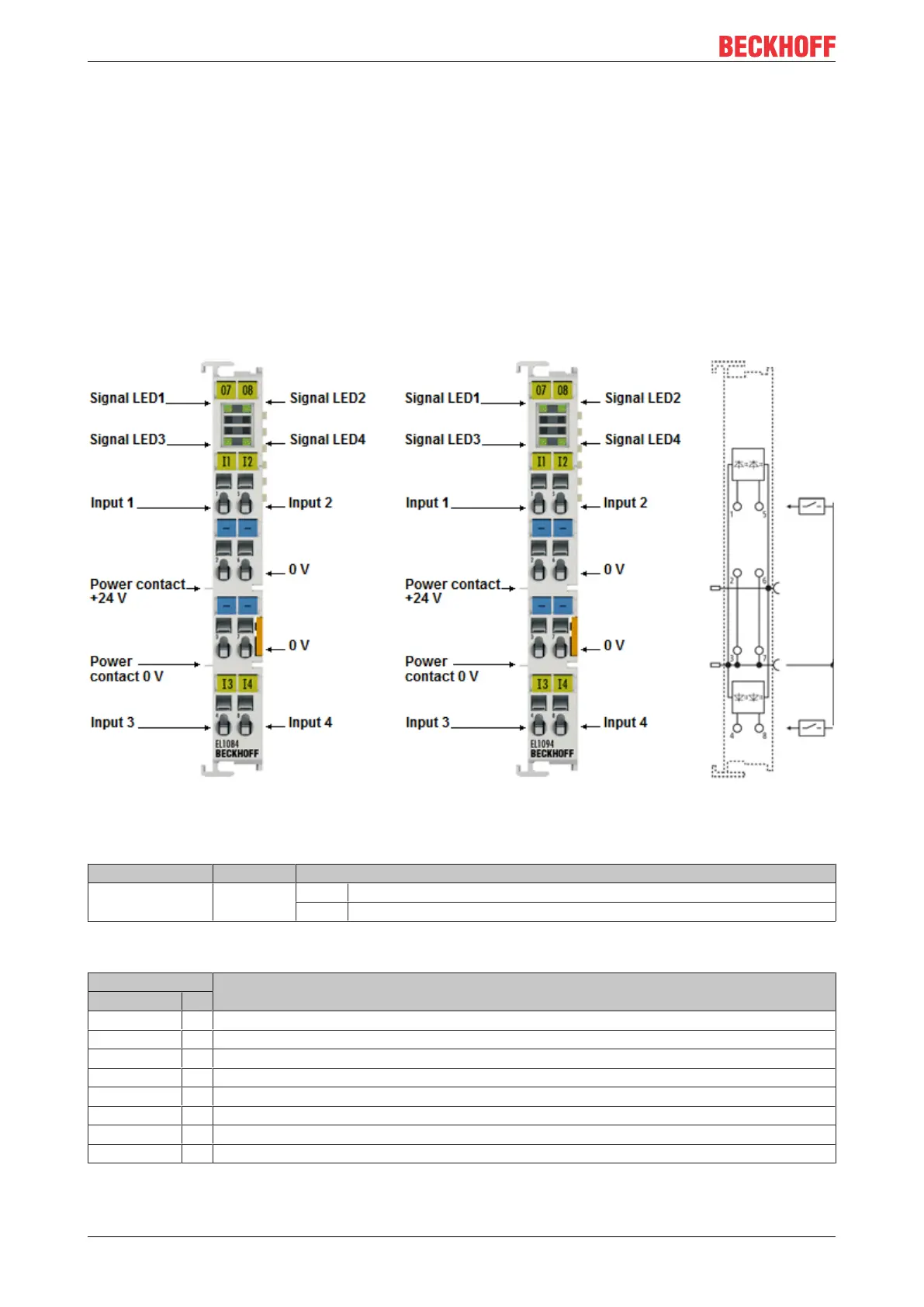
2.4.1 EL1084, EL1094 - LEDs and connection
Fig.18: EL1084, EL1094
EL1084, EL1094 - LEDs
LED Color Meaning
INPUT 1- 4 green off Signal voltage "0" (18V ... 30V)
on Signal voltage "1" (0V ... 7V)
EL1084, EL1094 - Connection
Terminal point Description
Name No.
Input 1 1 Input 1
0 V 2 0V (internally connected to terminal point3, 6, 7 and negative power contact)
0 V 3 0V (internally connected to terminal point2, 6, 7 and negative power contact)
Input 3 4 Input 3
Input 2 5 Input 2
0V 6 0V (internally connected to terminal point2, 3, 7 and negative power contact)
0V 7 0V (internally connected to terminal point2, 3, 6 and negative power contact)
Input 4 8 Input 4

 Loading...


