Product overview
EL10xx, EL11xx 19Version: 4.5
2.2 EL1012, EL1014, EL1018 - Introduction
Two-, four- and eight-channel digital input terminals 24V
DC
, 10µs input filter
The EL101x digital input terminals acquire binary control signals from the process level and transmit them, in
an electrically isolated form, to the higher-level automation device. They differ in the number of channels and
the pin assignment. The digital input terminals of the EL101x series feature an input filter (10µs) and
indicate their signal state through an LED for each channel.
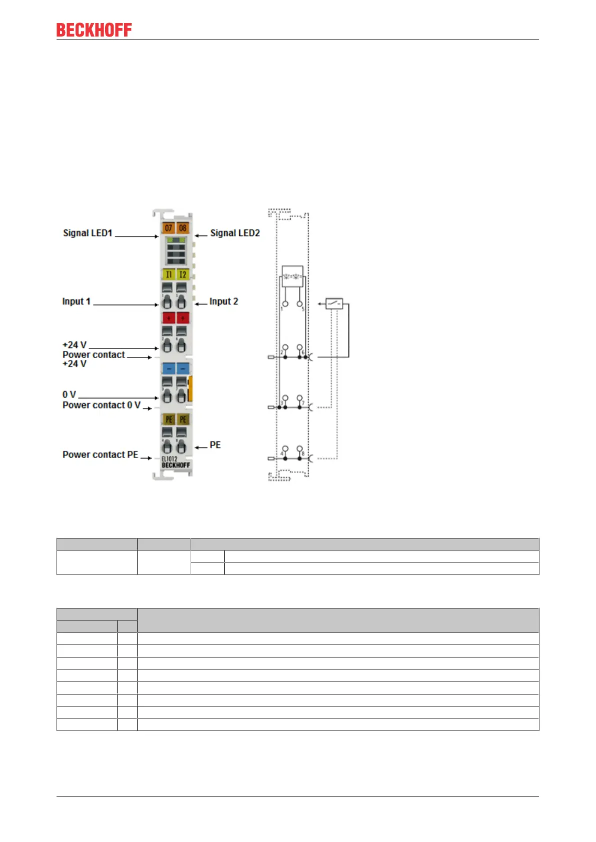
2.2.1 EL1012 - LEDs and connection
Fig.13: EL1012
EL1012 - LEDs
LED Color Meaning
INPUT 1
INPUT 2
green off Signal voltage "0" (-3V ... 5V)
on Signal voltage "1" (11V ... 30V)
EL1012 – Connection
Terminal point Description
Name No.
Input 1 1 Input 1
+24V 2 Sensor supply for input1 (internally connected to terminal point6 and positive power contact)
0 V 3 Ground for input1 (internally connected to terminal point7 and negative power contact)
PE 4 PE (internally connected to terminal point8)
Input 2 5 Input 2
+24V 6 Sensor supply for input2 (internally connected to terminal point2 and positive power contact)
0V 7 Ground for input2 (internally connected to terminal point3 and negative power contact)
PE 8 PE (internally connected to terminal point4)

 Loading...


