Product overview
EL10xx, EL11xx24 Version: 4.5
EL1024 - Connection
Terminal point Description
Name No.
Input 1 1 Input 1
+24V 2 Sensor supply for input1 (internally connected to terminal points3, 6, 7 and positive power contact)
+24V 3 Sensor supply for input3 (internally connected to terminal points2, 6, 7 and positive power contact)
Input 3 4 Input 3
Input 2 5 Input 2
+24V 6 Sensor supply for input2 (internally connected to terminal points2, 3, 7 and positive power contact)
+24V 7 Sensor supply for input4 (internally connected to terminal points2, 3, 6 and positive power contact)
Input 4 8 Input 4
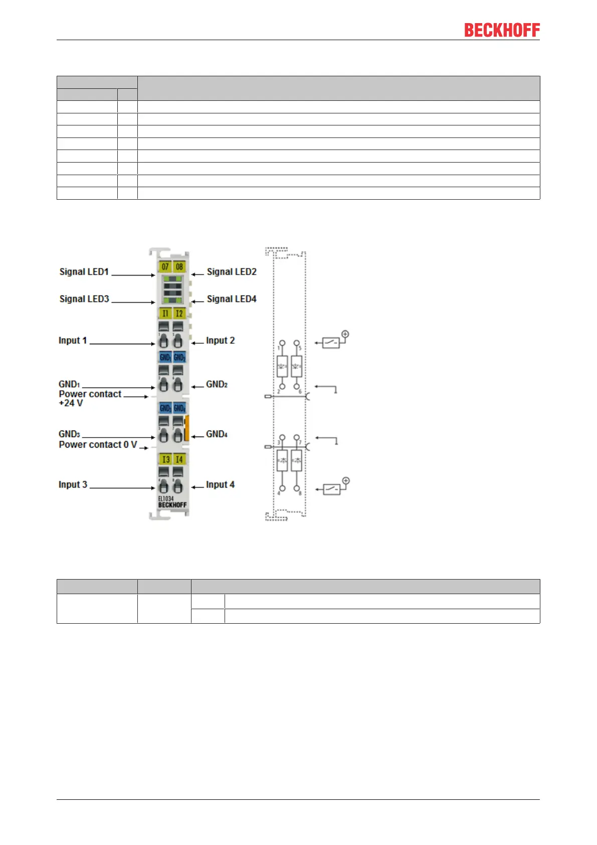
2.3.2 EL1034 - LEDs and connection
Fig.17: EL1034
EL1034 - LEDs
LED Color Meaning
INPUT 1- 4 green off Signal voltage "0" (-3V ... 5V)
on Signal voltage "1" (15V ... 30V)
 Loading...


