SAFE
If the Reset input is 1 and the Set input is 0, the FB SR module assumes the SAFE
state.
The outputs assume the following values:
SrOut=0
SET
If the Set input is 1, the FB SR module assumes the SET state.
The outputs assume the following values:
SrOut=1
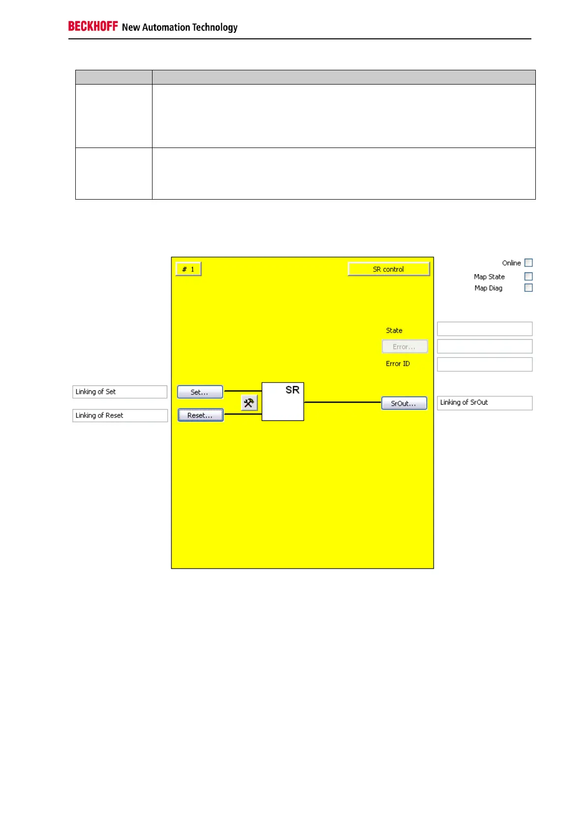
3.11.3 FB SR configuration in the TwinCAT System Manager
Figure 3-51: FB SR configuration
Use the Settings button to the right of the Reset and Set inputs to activate the input signals and configure
them as make contact (NO) or break contact (NC). In the default state both inputs are disabled.
The 'Reset' and 'Set' buttons can be used to link the input variables of the FB RS.
The 'SrOut' button can be used to link the output variable of the FB RS.
The error output is inactive since FB SR reports no error.
The 'MapState' and 'MapDiag' checkboxes are used to specify which FB diagnostic functions are mapped
to the cyclic process image.