Function blocks
176 Function blocks for TwinSAFE logic components
3.26.4 Application: pendulum mode
In pendulum mode both directions of rotation are permitted. Two upper reversal points are parameterized
here.
Since the curve based on which the press is to be moved can or must be adjusted for each product, the
maximum range of the oscillating stroke is set as the limits for the upper reversal points.
The lower reversal point (BDC) is set with an upper and lower limit.
In pendulum mode the system checks that the upper limits (TDC1 and TDC2) are never exceeded. If this
happens, the output CamMonOK is set to FALSE. At the start of the cycle (falling edge at Reset input) the
press may start with any motion (pulsating, reverse, ...) until the lower reversal point (BDC) is reached.
After this only upward movement is permitted. The upward movement is output as a signal
(UpwardsMove) at the function block.
A new start is enabled via the Reset input. If the press is in downward motion without a falling edge
having been detected at the Reset input, the system is stopped immediately by setting CamMonOK to
FALSE.
The optional function block inputs for connecting an upward or overrun cam are not supported in this
operation mode. An error is set if they are active erroneously.
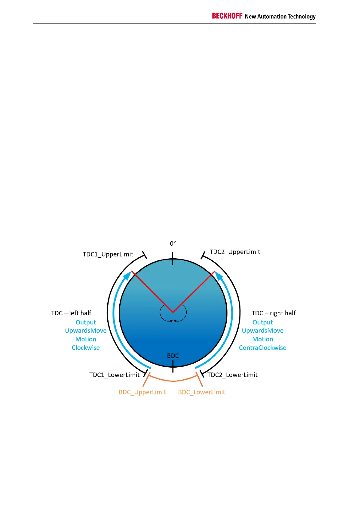
3.26.4.1 Schematic diagram of the ranges
Figure 3-118: Pendulum mode - schematic diagram of the ranges