Function blocks
Function blocks for TwinSAFE logic components 35
3.3 The function block OPMODE
3.3.1 Functional description
Operation mode selectors can be realized with the FB OPMODE. The function block has 8 inputs and 8
outputs, which are looped through one-to-one. Up to 8 different operation modes can be selected.
The FB OPMODE sets the corresponding output only if exactly one input is set ("1"). The other outputs
remain in the safe state ("0"). All outputs are in a safe state if there is none or more than one input is set.
If the restart input is enabled, the safe state of the outputs is only exited by a rising and falling edge at the
restart input during startup and when the operation mode changes (see also chapter 3.3.4 Restart
behavior). No time monitoring of the restart signal takes place. The output is switched on when the restart
signal changes from TRUE to FALSE.
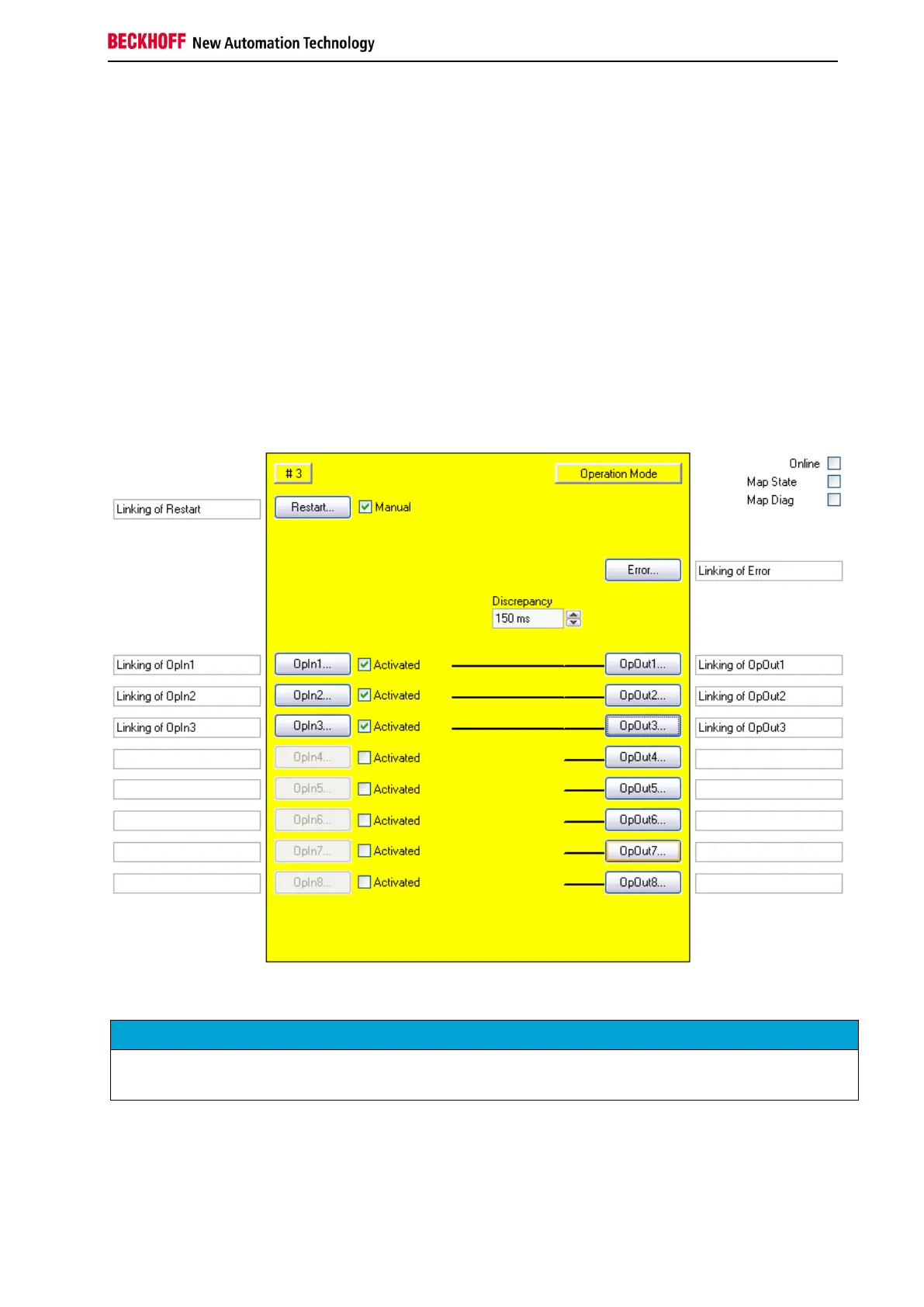
A discrepancy time can be specified to monitor the change from one operation mode to the next.
Figure 3-9: Function block OPMODE