Function blocks
114 Function blocks for TwinSAFE logic components
3.14.2 Signal description
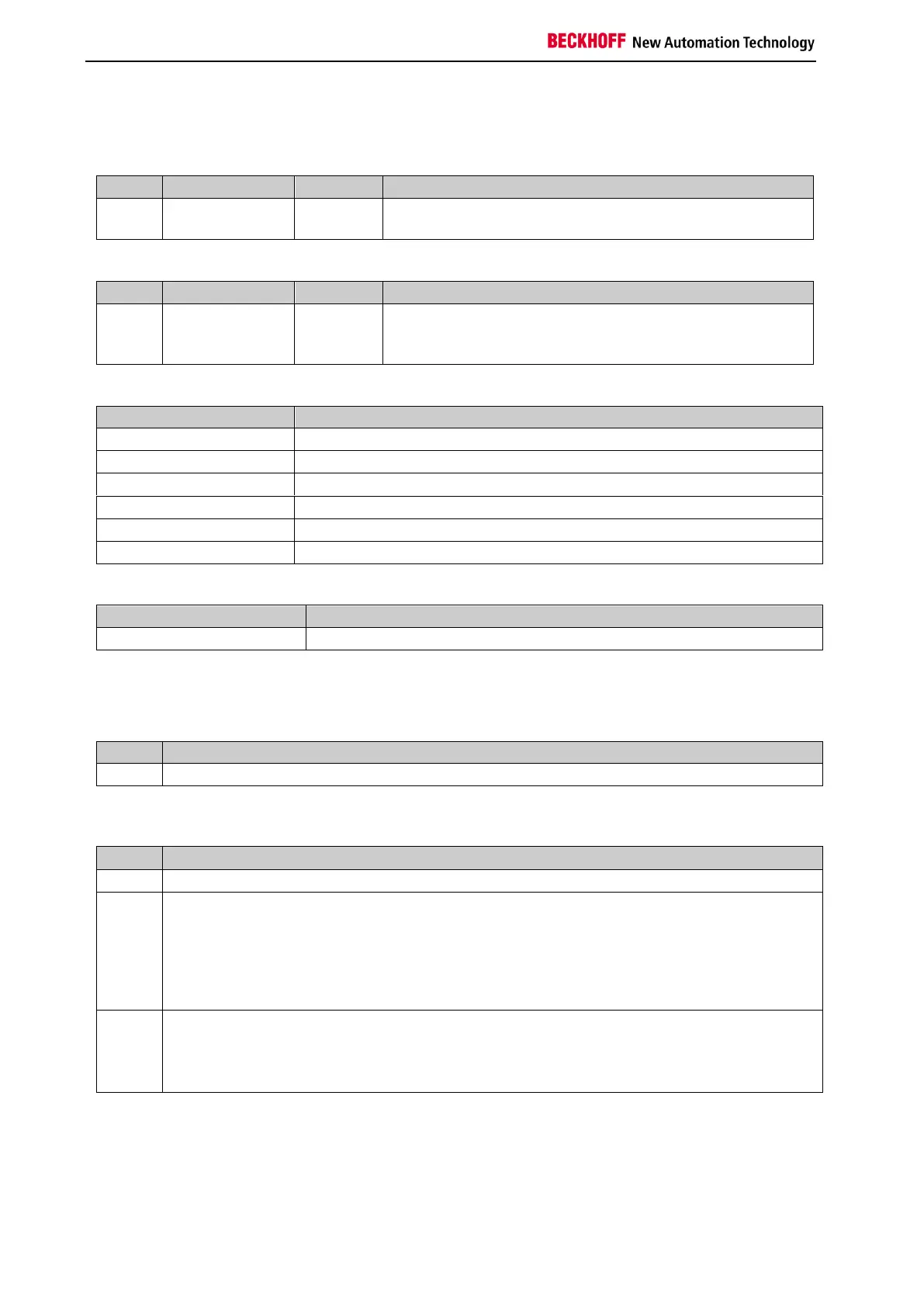
Table 3-80: FB TOF inputs
1st input channel; the parameterization indicates whether a
break contact or a make contact is linked to this input.
Table 3-81: FB TOF outputs
TwinSAFE-Out
FB-In
Standard-Out
1st output channel, the safe state corresponds to a logical
0.
Table 3-82: Input and output types
TwinSAFE input, e.g. at an EL1904/KL1904
Standard PLC variable (output in the PLC %Q*)
TwinSAFE output, e.g. at an EL2904/KL2904
Standard PLC variable (input in the PLC %I*)
Table 3-83: Internal identifier of the FB
This description applies to BLG 1.0 (internal version number)
3.14.2.1 Diagnostic and state information for FB TOF
Table 3-84: Diagnostic information (16-bit value)
Table 3-85: State information (8-bit value)
RUN
If the TimerIn input is 1, the FB TOF module assumes the RUN state. If the TimerIn changes
to 0 in the RUN state, the FB TOF module starts the delay timer with the DelayTime and
changes to the DELAYOUT state.
The outputs assume the following values:
TimerOut=1
STOP
The FB TOF module assumes the STOP state if the input FbRun is FALSE.
The outputs assume the following values:
TimerOut=0