EasyManua.ls Logo

Beckhoff TwinSAFE logic FB User Manual

Beckhoff TwinSAFE logic FB
217 pages
To Next Page IconTo Next Page
To Previous Page IconTo Previous Page
Page #152 background imageLoading...
Page #152 background image
Function blocks
150 Function blocks for TwinSAFE logic components
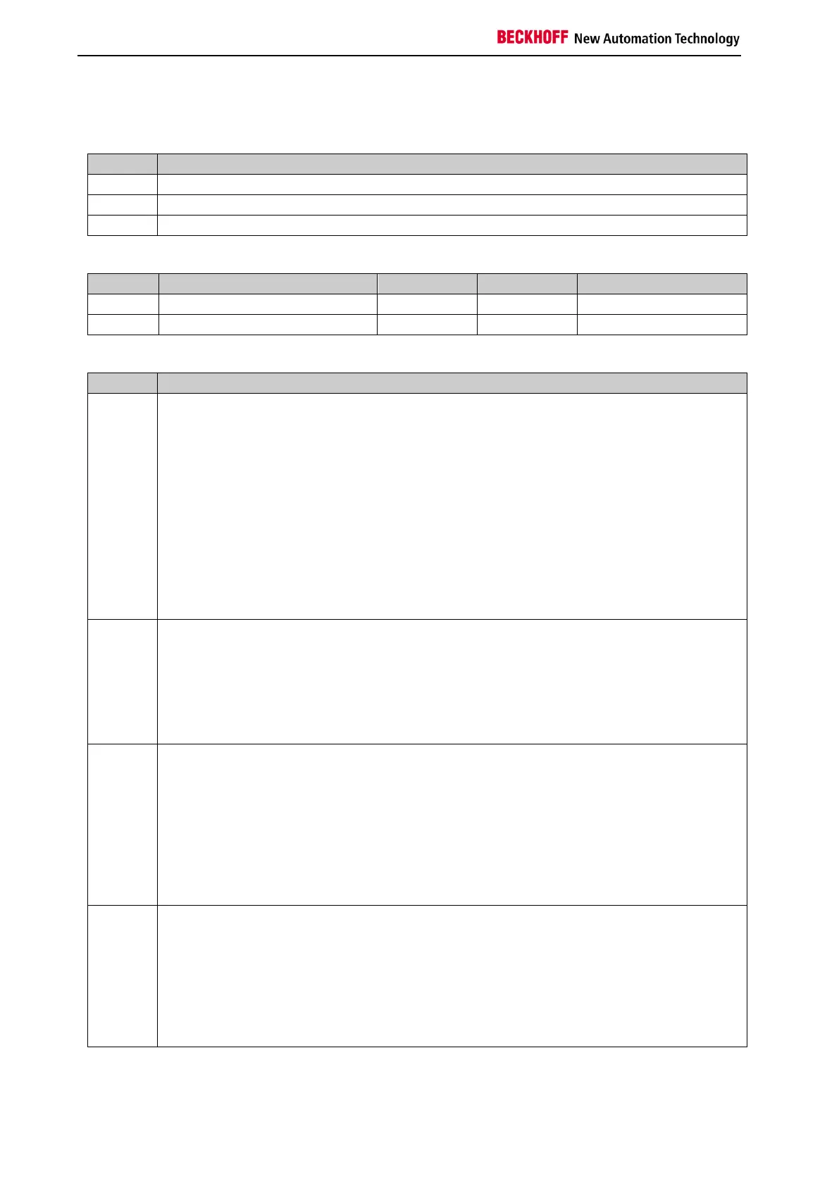
3.22.2.1 Diagnostic and state information for the FB Counter
Table 3-138: Diagnostic information
Value
Description
0
No diagnostic information
1
The ActValue output has an underflow (is less than the smallest possible value)
2
The ActValue output has an overflow (is greater than the largest possible value)
Table 3-139: Diag Message
Text ID
Meaning
Parameter 1
Parameter 2
Parameter 3
0x40B8
An underflow has occurred
FB number
ActValue
Smallest permitted value
0x40B9
An overflow has occurred
FB number
ActValue
Largest permitted value
Table 3-140: State information
Value
Description
1
RUN
In the RUN state the FB COUNT module sets the ActValue output to PresetValue if the
Reset input is TRUE.
If the Reset input is FALSE, the FB COUNT module increments the ActValue output when a
rising edge is detected at the CountUp input and decrements it when a rising edge is
detected at the CountDown input (this means ActValue remains unchanged when both
CountUp and CountDown inputs detect a rising edge).
The outputs assume the following values:
Error=0
CounterOut=(ActValue >= CounterLimit)
CounterZero=(ActValue == 0)
Reset=TRUE: ActValue=PresetValue
Reset=FALSE: ActValue=ActValue+n (-1 <= n <= 1)
2
STOP
The FB COUNT module assumes the STOP state if the input FbRun is FALSE.
The outputs assume the following values:
Error=0
CounterOut=0
CounterZero=0
ActValue=0
4
ERROR
If the FB COUNT module detects an error while checking the value range of CounterOut,
the FB COUNT module switches to the ERROR state and transmits the corresponding Diag
message to the GROUP module.
The outputs assume the following values:
Error=1
CounterOut=0
CounterZero=0
ActValue=0
5
RESET
The FB COUNT module assumes the RESET state if no further error is pending after an
error has occurred and the ErrAck input of the corresponding group is set to TRUE.
The outputs assume the following values:
Error=0
CounterOut=0
CounterZero=0
ActValue=0

Table of Contents

Question and Answer IconNeed help?

Do you have a question about the Beckhoff TwinSAFE logic FB and is the answer not in the manual?

Beckhoff TwinSAFE logic FB Specifications

General IconGeneral
BrandBeckhoff
ModelTwinSAFE logic FB
CategoryIndustrial Electrical
LanguageEnglish

Summary

1 Foreword

Notes on the Documentation

Information regarding the documentation's target audience, origin, currentness, and symbols used.

Safety Instructions

Guidance on safety instructions, delivery state, operator diligence, and explanation of notes.

2 System Description

TwinSAFE Logic Terminals and Connections

Details on TwinSAFE logic terminals, groups, connections, and configuration. Includes diagnosis overview.

System Diagnosis

Information on diagnosing TwinSAFE system components, including diagrams for TwinCAT 2 and TwinCAT 3.

3 Function Blocks

The Function Block AND

Functional description, signal details, diagnostic info, and TwinCAT configuration for the AND logic block.

The Function Block OR

Functional description, signal details, diagnostic info, and TwinCAT configuration for the OR logic block.

The Function Block OPMODE

Description of OPMODE function block for operation mode selection and restart behavior.

The Function Block ESTOP

Details on ESTOP function block: description, signals, configuration, restart behavior, and extensions.

The Function Block MUTING

Description of MUTING block, signals, configuration, examples, and extensions for EL/EJ6910.

The Function Block TON

Functional description, signal details, diagnostic info, and TwinCAT configuration for the TON delay timer.

The Function Block TOF

Functional description, signal details, diagnostic info, and TwinCAT configuration for the TOF delay timer.

The Function Block ADD

Description of ADD block for analog addition: signals, diagnostics, and TwinCAT configuration.

The Function Block SUB

Description of SUB block for analog subtraction: signals, diagnostics, and TwinCAT configuration.

The Function Block COMPARE

Description of COMPARE block for analog input comparison, including architectures, signals, and config.

The Function Block LIMIT

Description of LIMIT block for checking analog input values against Min/Max limits, including signals and config.

The Function Block COUNTER

Description of COUNTER block for up/down counting: signals, diagnostics, and TwinCAT configuration.

The Function Block CAMMONITOR

Description of CAMMONITOR block for electronic cam control: modes, inputs, outputs, parameters, and diagnostics.

4 Appendix

Beckhoff Support and Service

Information on contacting Beckhoff for technical support, system solutions, and after-sales service.

Beckhoff Headquarters Information

Contact details, phone, fax, email, and web address for Beckhoff Automation GmbH & Co. KG.

Related product manuals