Function blocks
42 Function blocks for TwinSAFE logic components
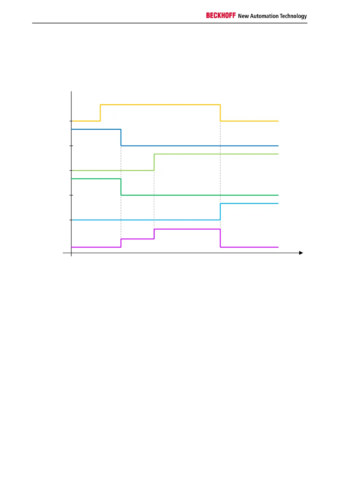
In the following diagram the Restart is set to TRUE before the operation mode change takes place.
Changing the input OpIn1 from TRUE to FALSE results in a switch to state 3. Once operation mode
OpIn2 is TRUE, the system changes to the Start state (FB state 6), since the Restart input is already
TRUE. The output OpOut2 is activated by changing the Restart input from TRUE to FALSE.