EasyManuals Logo

Beckhoff TwinSAFE logic FB User Manual

Beckhoff TwinSAFE logic FB
217 pages
To Next Page IconTo Next Page
To Previous Page IconTo Previous Page
Page #53 background imageLoading...
Page #53 background image
Function blocks
Function blocks for TwinSAFE logic components 51
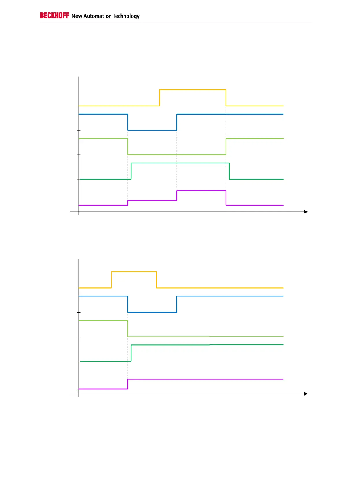
The following diagram shows the behavior of the ESTOP function block, where the change of the Restart
signal from FALSE to TRUE takes place before the change of the EStop inputs from FALSE to TRUE.
The Start state (FB state 6) is only assumed if both signals are TRUE. The output is enabled when the
Restart input changes from TRUE to FALSE. At least one of the EDM inputs of the FB is active.
RESTART
Estop-In
EStopOut
EDM
FB State
State 1
State 3
State 6
State 1
In the following diagram the Restart input is set to TRUE before the emergency stop event takes place.
Due to the Restart input signal, the EDM signal is checked immediately when the EStop-In input changes
from TRUE to FALSE. This immediately leads to an EDM error and to the shutdown of the entire
TwinSAFE group.
RESTART
Estop-In
EStopOut
EDM
FB State
State 1
State 4 (Error Diag 0001 0000)

Table of Contents

Questions and Answers:

Question and Answer IconNeed help?

Do you have a question about the Beckhoff TwinSAFE logic FB and is the answer not in the manual?

Beckhoff TwinSAFE logic FB Specifications

General IconGeneral
BrandBeckhoff
ModelTwinSAFE logic FB
CategoryIndustrial Electrical
LanguageEnglish

Related product manuals