© BEKA 201 All rights reserved!6
...a product of BEKA
1
2
3
2
1
Attention!
1
1
31
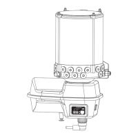
Connecting outlets:
Remove the screwed sealing plugs (1, Fig. 35 or 1, Fig. 36).
Remove the cylinder screws and sealing rings (1, Fig. 34).
Refit the screwed sealing plug (1, Fig. 36 or 4, Fig. 34).Ensure that the sealing ring has a clean fit in the hole.
If the sealing ring and the screwed sealing plug are not properly screwed back in, water or dirt may
get into the central lubrication pump and be carried into the lubrication system, where damage may
occur.The system is no longer leak-tight and cannot build up pressure.
Fig. 35: Fig. 36:
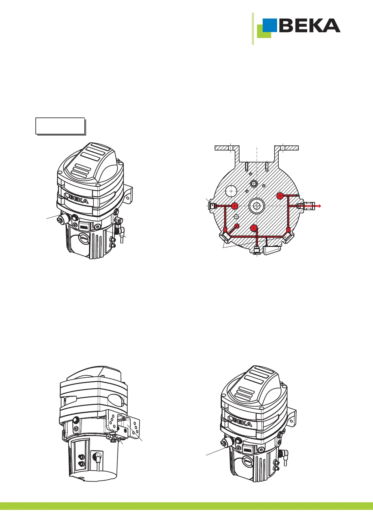
8.3.3 Example 2: Combining the delivery volumes of all outlets and routing out of outlet 4:
General:
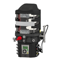
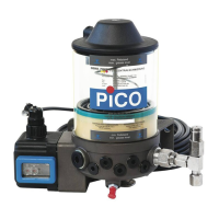
Outlet 4 (1, Fig. 37) is located on the back of the central lubrication pump. To be able to use this outlet, a connection block
must be fitted (2, Fig. 37) (15. 16. ).spare part list and spare part drawing
The central lubrication pump must be equipped with a dummy cover for the pressure connection at the back (3, Fig. 38).
Apump element PE-250 G without pressure limiting valve ( ig. 33) must be installed in all used outlet positions.F
All outlets must be sealed with a screwed sealing plug (2, Fig. 39).
In outlet 4, an outlet fitting must be installed (1, Fig. 37).
The pump must be equipped with an integrated pressure limiting valve (version ball valve) (Fig. 33).
Fig. 37: Fig. 38: