© BEKA 201 All rights reserved!6
...a product of BEKA
17
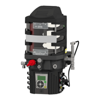
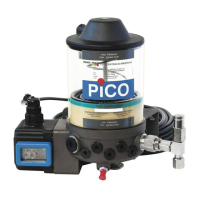
7.4.4 Function of the pump GIGAPLUS for the use in single line lubrication systems
Single line lubrication systems lubricants up to NLGI-cl. 2are supplied with . The agitator blade presses lubricant
through the grease filter into the suction chamber of the pump element. The are actuated compulsory bypump elements
the eccentric.
When using the central lubrication pump GIGA PLUS as , only 1 lubrication cyclesingle line central lubrication pump
can be connected. The or an that is connected with the lubricationinstalled pressure switch external pressure switch
system and a are supposed to switch over the main line (pressure setup or relieve).magnetic valve
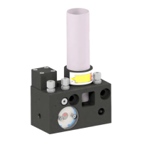
Up to three pump elements can be installed in the pump (see 7.5 pump elements). The total delivery rate can be
modified by combining the delivery rates of the pump elements (see 8.3 combination of outlets), in case the pump
elements are installed without safety valves. The combined delivery rate can be provided at each outlet. Non-used outlets
must be closed with a screw plug (see 15 spare part list and 16 spare part drawing).
In case of an error the pressure is limited by a installed at the pump or apressure limiting valve (version piston valve)
pressure limiting valve (version ball valve) pump elementthat is installed at the ( ig. 11).F
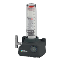
It is possible to equip the pump with an for the ( ig. 6). If the grease falls below aintegrated level monitoring min. level F
certain level external signal transmitter, the level switch switches off the signal. The shall switch off the pump to avoid
that air gets into the system.
7.4.5 Function of the pump GIGAPLUS for the use in dual line lubrication systems
Dual line lubrication systems lubricants up to NLGI-cl. 2are supplied with . The agitator blade presses lubricant
through the grease filter into the suction chamber of the pump element. The are actuated compulsory bypump elements
the eccentric.
When using the central lubrication pump GIGAPLUS as , only 1 lubrication cycledual line central lubrication pump
can be connected. Two es and two magnetic valves are supposed to switch over the maininstalled pressure switch
lines (pressure set up or relief).
system and a are supposed to switch over the main line (pressure setup or relieve).magnetic valve
Each main line needs an own pump element (see 7.5 pump elements). They are installed in outlet 1 and 3 as standard.
In case of an error the pressure is limited by a that is directly installed at thepressure limiting valve (version ball valve)
pump element ( ig. 11).F
It is possible to equip the pump with an forthe ( ig. 6). If the grease falls below aintegrated level monitoring min.level F
certain level external signal transmitter, the level switch switches off the signal.The shall switch off the pump to avoid
that air gets into the system.