Do you have a question about the BEKA BEKA-MAX GIGA and is the answer not in the manual?
General safety warnings and symbols for hazards like voltage, hot surfaces, etc.
Requirements for personnel operating, maintaining, or assembling the pump.
Risks to persons, environment, and device from not following safety guidelines.
Customer responsibilities regarding safety, leakages, legal provisions, and pipe maintenance.
Guidelines for safe execution of maintenance, inspection, and assembly tasks.
Manufacturer's stance on modifications and use of non-original parts, affecting safety and liability.
Warning against using the device outside its specified operational limits or intended use.
Precautions to prevent damage to electronic components from static electricity.
Awareness of potential hazards even with compliant systems, emphasizing proper use and inspection.
Explanation of how progressive systems work, including pump, distributors, and lubricant flow.
How the pump supplies single line systems, including pressure switch and valve functions.
Details on dual line lubrication systems, pump elements, and pressure switches.
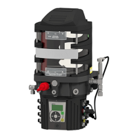
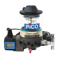
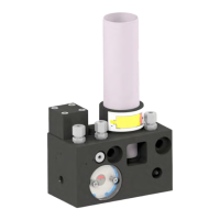
Overview of the pump's main components and general layout.
Description of GIGA pump operation, delivery volumes, and level monitoring.
Description of GIGA PLUS pump operation, delivery, and pressure/level monitoring.
How GIGA PLUS operates in single line systems, including pump elements and monitoring.
How GIGA PLUS operates in dual line systems, including pump elements and pressure/level monitoring.
Details on PE-120 G and PE-250 G pump elements, delivery rates, and connections.
Specifics on GIGA PLUS pump elements, including pressure limiting valves and microswitches.
Explanation of pressure limiting valves for system protection and safety precautions.
Information on pump elements equipped with microswitches for electronic monitoring.
Options for ordering pump outlets with different fittings.
Description and function of the integrated minimum level monitoring device.
Function of the momentum sensor for monitoring pump revolutions.
Role of magnetic valves in relieving main lines in single and dual line systems.
Function of integrated pressure switches in single line systems for pressure control.
Checks before assembly, installation conditions, and general mounting advice.
Step-by-step guide for removing and installing pump elements.
How to combine delivery rates of GIGA PLUS pump elements and discharge options.
Detailed description of pump outlets, non-return valves, and pressure limiting valves.
Specific steps to combine all outlet volumes and discharge from outlet 1.
Specific steps to combine all outlet volumes and discharge from outlet 4.
Guidelines for professional pipe assembly, pressure tightness, and component suitability.
Instructions for safe and correct electrical connection by qualified personnel.
Electrical diagrams for connecting pumps with bayonet and cubic plugs.
Wiring details for microswitch connections on pump elements.
Wiring diagram for the level monitoring device.
Wiring diagram for the momentum sensor.
Electrical diagrams for dual line systems with cubic plugs.
Important precautions for filling the lubricant reservoir, emphasizing cleanliness and correct lubricant.
Method for filling the reservoir using a grease gun and nipple.
Method for refilling the reservoir using a refill coupling.
Method for filling the reservoir using a filler gun.
Procedures for ventilating progressive and single line lubrication systems.
How to check and correct pump rotation direction to avoid damage.
Routine checks like retightening fittings and inspecting for leaks and damage.
Guidelines for refilling lubricant, checking levels, and lubricant quality.
Step-by-step guide for replacing level switches and momentum sensors.
Procedure for replacing the cable connected to the momentum sensor.
Steps to replace integrated pressure limiting valves in GIGA PLUS for progressive systems.
Guide for replacing magnetic valves or pressure switches in single line systems.
Procedure for replacing pressure switch cables.
Procedure for replacing magnetic valve cables.
Guide for replacing magnetic valves or pressure switches in dual line systems.
Procedure for replacing magnetic valve cables 1 and 2.
List of spare parts for GIGA pumps in progressive systems.
Spare parts list for GIGA PLUS pumps in progressive systems.
Spare parts list for GIGA PLUS pumps in single line systems.
Spare parts list for GIGA PLUS pumps in dual line systems.
Exploded view diagram of GIGA pump parts for progressive systems.
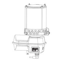
Exploded view of lubricant reservoirs for GIGA and GIGA PLUS pumps.
Exploded view diagram of GIGA PLUS pump parts for progressive systems.
Exploded view diagram of GIGA PLUS pump parts for single line systems.
Exploded view diagram of GIGA PLUS pump parts for dual line systems.
Guide to constructing the order code for GIGA pumps in progressive systems.
Guide to constructing the order code for GIGA PLUS pumps in progressive systems.
Ordering information for motor covers for GIGA/GIGA PLUS in progressive systems.
Guide to constructing the order code for GIGA PLUS pumps in single line systems.
Ordering information for motor covers for GIGA PLUS in single line systems.
Guide to constructing the order code for GIGA PLUS pumps in dual line systems.
Ordering information for motor covers for GIGA PLUS in dual line systems.
| Motor Power | 1.5 kW |
|---|---|
| Voltage | 230/400 V |
| Weight | 18 kg |
| Frequency | 50 Hz |
| Category | Water Pump |
| Max Flow Rate | 50 m³/h |
| Power | 1500 W |