© BEKA 201 All rights reserved!6
...a product of BEKA
11.4 Exchange of magnetic valve and/or pressure switch at lubrication pump GIGA PLUS for the use in single
line lubrication sytsems
a) Proceed as described in item 11.1 pos. a to c .
b) Loose the cable from the pressure switchs and/or magnetic valve on the board.
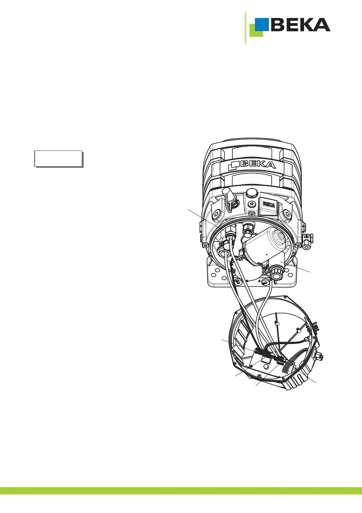
c) Remove the pressure switch (Fig. 54, pos. 1) and/or the magnetic valve (Fig. 54, pos. 2) and replace the
pressure switch and/or the magnetic valve by a new one (see 15.3 spare part list and 16.4 spare part drawing).
The magnetic valve always has to be
installed next to the used outlet (Y1 for
outlet 1, Y2 for outlet 2,Y3 for outlet 3)
Connection of cable:
d) Plug the motor cable into the plug type connection
X2 of the board (Fig. 54).
e) Plug the pressure switch cable into the plug type
connection X6 of the board (Fig. 54).
f) Connect the magnetic valve cable with the plug with
two cable looms at the plug type connection X199 of
the board (Fig. 54).
g) Connect the magnetic valve cable with the plug with
one cable loom at the plug type connection for the
power plug (Fig. 54).
h) Plug the level switch at the plug type connection X5
of the board if available (Fig. 54).
i) Proceed as described under item 11.1 pos. i and j.
11.5 Exchange pressure switch cable
a) Proceed as described under item 11.1 pos. a to c.
b) Remove the pressure switch cable and replace it with a new one (see 15.3 spare part list and 16.4 spare part
drawing) Proceed as described under item 11.4.
c) Proceed as described under item 11.1 pos. i and j.
11.6 Exchange magnetic valve cable
a) Proceed as described under item 11.1 pos. a to c.
b) Remove the magnetic valve cable and replace it with a new one (see 15.3 spare part list and 16.4 spare part
drawing). Proceed as described under item 11.4 pos. f and g.
c) Proceed as described under item 11.1 pos. i and j.
Fig. 54:
1
2
X2
X6
X199
X5
Note!
41