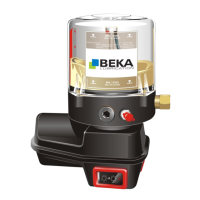
Do you have a question about the BEKA EP-1 and is the answer not in the manual?
Details conditions under which warranty claims may be invalidated due to improper use or components.
Covers general safety, risk references, personal qualifications, and training requirements.
Encompasses intended use, liability, assembly safety, operator safety, electrical/pressure hazards.
Includes guidelines for modifications, spare parts, and hydraulic hose lines.
Specifies suitable grease types, environmental hazards, and handling precautions.
Defines inadmissible operation methods and provides guidelines for pump transport and storage.
Lists electrical and performance data for EP-1, FKGGM-EP, and FKGGM-EP with PSU motors.
Details pump pressure, temperature, reservoir sizes, installation, and protection type.
Provides operating voltage, current load, fuse, and temperature for BEKA-troniX1, EP-tronic T1, and EP-T2 control units.
States conditions for safe and health-conscious assembly of the pump into a complete machine.
Covers safety for pipeline assembly and expert electrical connections.
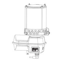
Provides detailed dimensional drawings for pumps with steel reservoirs of different capacities.
Shows side and top-view installation dimensions for pumps with transparent reservoirs of various capacities.
Details installation dimensions and views for pumps with 8 kg and 16 kg reservoirs.
Shows the wiring for pumps without an integrated control unit, using a simple connection.
Illustrates the wiring for EP-1 pumps with a special bayonet connector.
Details the terminal connections for BEKA-troniX1 and EP-tronic T1 control units with various options.
Provides wiring diagrams for the EP-T2 and EP-tronic control units with multiple options and signals.
Advises checking the power supply unit voltage indicated on the motor shell sticker.
Explains system operation, sequential delivery, and pressure relief valve protection.
Details general pump operation, control without unit, PE-120 V function, and level monitoring.
Shows proximity switch connection diagrams and technical data for external control and cubic plug types.
Covers AC wiring, function, hazards, terminal diagrams, and technical data for the micro switch.
Details output rates, order numbers, and fixed pressure relief settings for standard pump elements.
Describes the PE-120 V element, its adjustable output rate, and provides an output rate graph.
Explains how to adjust delivery rate, install/remove elements, and ventilate the pump.
Describes the visual indicator that shows when operating pressure exceeds 280 bar.
Explains how these units operate based on lubrication and cycle times, including LED indicators and data memory.
Covers intermediate lubrication, malfunction reset, and comparison of time vs. revolution control.
Explains cycle control based on counting distributor piston strokes via a proximity switch and its technical data.
Lists values saved in BEKA-troniX1 and EP-tronic memory, accessible via BEKA-DiSys.
Details how modes and ranges are adjusted using diagnostic software and lists BEKA-troniX1 ranges.
Lists EP-tronic ranges and instructs on sticker exchange after setting changes, with orderable sticker sets.
Details optional grease level monitoring with proximity switch and pressure relief valve monitoring with micro switch, including technical data.
Covers starter release, collective fault signals, external indicators, and adapting EP-tronic for load conditions.
Explains T1 operation, load-based cycle time adjustments, and summing lubrication times.
Details EP-tronic adjusting ranges via BEKA-DiSys and provides information on ordering custom labels.
Explains how the EP-T2 unit limits lubrication based on brake signals, including interruptions.
Details how to adjust control unit parameters and warns about water entry if covers are not replaced properly.
Describes standard filling, filler coupling, filling press, and emphasizes cleanliness and lubricant quality.
Explains LED indicators for pump functions, errors, and test lubrication, including how to activate permanent lubrication.
Provides a step-by-step guide for ventilating the pump if the reservoir is emptied by mistake.
Covers safety precautions for maintenance, regular visual inspections, and authorized personnel.
Advises heeding lubricant manufacturer's advice and regional regulations for pump disposal.
Diagram showing exploded view of parts for the 1.9 kg reservoir assembly.
Highlights the cable used for grease level monitoring across various reservoir sizes.
Exploded view of parts for the 2.5 kg reservoir assembly.
Diagram showing exploded view of parts for the 4 and 4.2 kg reservoir assemblies.
Exploded view of parts for the 8 kg reservoir assembly.
Diagram showing exploded view of parts for the 16 kg reservoir assembly.
Lists parts including pump housing, motor housing, DC gear motors, and connection elements.
Details order numbers for pump elements (PE-60, PE-120, PE-170, PE-120 V) and pressure relief valves.
Details bayonet connectors, sealing, and motor housing parts with integrated control units or PSU.
Details parts for 1.9 kg and 2.5 kg reservoirs, including covers, connectors, and levels.
Lists components for 4 and 4.2 kg reservoirs, such as agitator blades, O-rings, and screws.
Details components for 8 kg and 16 kg reservoirs, including stickers, nuts, and covers.
Defines selection codes for temperature range, voltage, reservoir size, connection type, cable, and switch type.
Lists codes for connector version, additional equipment, parameter combinations, and fault signals for EP-tronic.
Lists codes for EP-tronic T1 connector version, settings, parameter, and cycle time combinations.
Lists codes for BEKA-troniX1 connector version, additional equipment, parameter, and cycle time combinations.
Specifies codes for EP-T2 connector version, lubrication time range, and special models.
Covers issues like pump not operating, no lubricant supply, no grease collar, and reduced pump speed.
Addresses leakage at pressure relief valve, indicator pin/LED errors, level errors, and function mismatches.
| Brand | BEKA |
|---|---|
| Model | EP-1 |
| Category | Water Pump |
| Language | English |