BAL_2152_EP1_Central grease lubrication pump_0816_EN EDV-Nr. 1090200430
Adjusting the delivery rate:
-
All pump elements are set to full stroke by the manufacturer.
-
Remove screw plug (2) withAllen key (A/F 5).
-
Set screw (3) can be turned with a screwdriver.
-
Turning clockwise reduces the output rate.
-
Turning counter-clockwise increases the output rate.
-
Maximum stroke of set screw is 2.4 mm = 6 notches.
-
1 turn of set screw is 0.8 mm = 2 notches.
-
Tighten screw plug (2) incl. sealing ring.
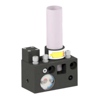
10.3. Installation and removal of the pump elements:
-
Only install / remove when pump is off.
-
Install pump element with partially extended piston (4) and insert it at an angle into the housing
drilling(see diagram A).
-
When the piston head rests on pressure ring - move element into vertical position (see
diagram B).
-
Piston head must run in guide ring groove.
-
Tighten the pump elements.
-
For removal, reserve above sequence.
-
When removing the pump element, ensure that the piston (4) is not left behind in the pump
housing.
The pump element or the pump are destroyed at first operation, if the pump
element has not been positioned correctly.
10.4 Ventilation of the pump
- Remove screw plug (2) withAllen key (A/F 5).
- Screw the adjusting screw (3) by means of a screw driver until stop
- Start the pump
- Screw back the adjusting screw (3) by 1 notch per revolution of the agitator blade
- Operate the pump until oil comes out of the screw plug thread
-Assemble the screw plug (2) incl. sealing ring and tighten it
Diagram A: Diagram B:
4
Attention!
2
21
EN
BEKA 2016 All rights reserved!