BAL_2152_EP1_Central grease lubrication pump_0816_EN EDV-Nr. 1090200430
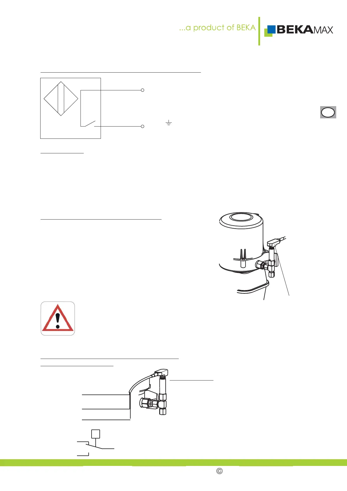
Wiring diagram with supply voltage of 90-250 V AC:
Pole assignment:
Compact plug connection, 3 poles+ PE
No. 1 = L1
No. 2 = free
No.3=Q
= yellow/green (only for max.)
Technical data:
Supply voltage: 90 to 250 V AC
Connecting method: NO contact (Tyristor outlet)
Switching current: at 70°C: min. 5 mA
max. mA250
Protection class: switch: IP 67
plug: IP 54
Ambient temperature range: -25°C to +70°C
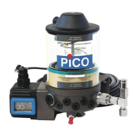
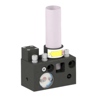
9.3.3. Micro switch at pressure relief valve:
The micro switch at the pressure relief valve is used for
monitoring the maximum operating pressure in the central
lubrication system.
If a malfunction occurs in the system, the micro switch is
actuated.
The micro switch signal can be processed by any already
existing signal encoder, e. g. an on-board controller, or by
an external or integrated control unit.
The lubricant comes out under high pressure (250 bar)!
Wear safey goggles and also do not stay otherwise within the area of the pressure
relief valve in the case of a malfunction of the central lubrication unit!
Never work when the voltage (ignition) of central lubrication system or pump is
connected! Relieve the central lubrication system before you start the works!
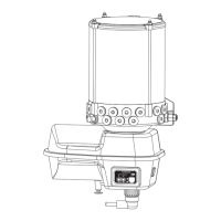
Terminal diagram for connecting the micro switch
to an external control unit:
brown
blue
L1
Q
Micro switch
black
brown
blue
Apparent ohmic
resistance
NC (normally closed
contact)
NO (normally open
contact)
Technical data:
Supply voltage: 10 to 60 V DC
max. current load: I = 1,7 A
Contact type: 1 changeover switch
Temperature range: -25° C to +85° C
Protection class: IP 67
Connection: Cable, length 0.5 m, welded
P
brown
blue
black
19
EN
BEKA 2016 All rights reserved!