Subject to alterations!
...a product from
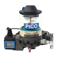
BAL2076_central lubrication pump_0119EN
© BEKA 2019 All rights reserved
1. Number cable:
+Ub = wire 1
Ground = wire 2
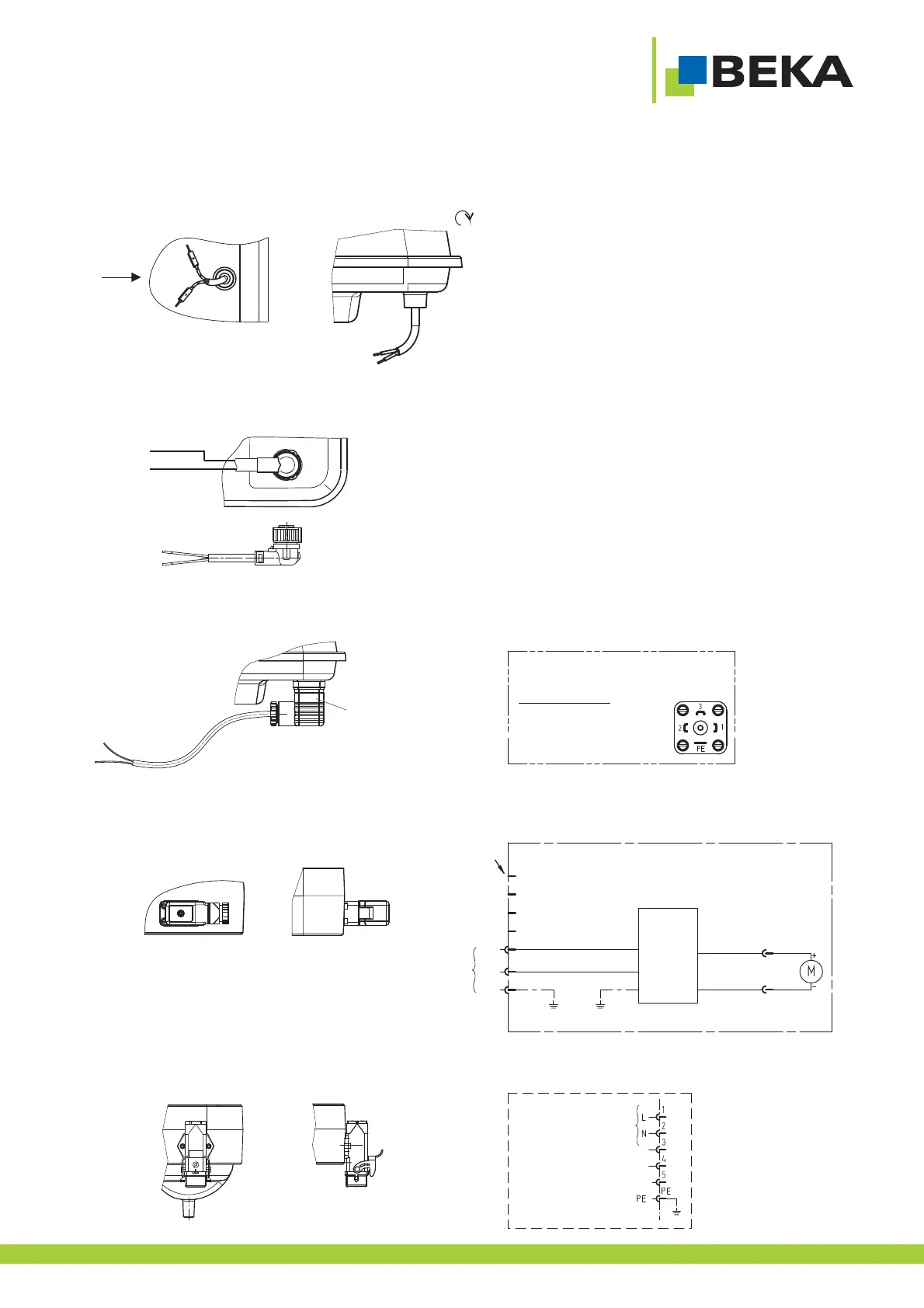
7.1 Connection central lubrication pump FKGGM - EP or EPR without control unit:
Fig. 48:
7.1.1 12 / 24V DC with line connection:
100-250 V AC
X1
L
N
PE
7
6
5
4
3
2
1
black 0,75
2
blue 0,75
2
L
N
PE
green 0,75
2
red 0,75
2
Power supply unit
RS-100-24
green
red
1
2
X2
24V
4,5A
+24V
GND
K1296
2. Color cable (2-cores)
+Ub = blue
Ground = brown
L = Pin 5
N = Pin 6
PE = Pin 7 (PE)
7.1.3 12 / 24 V DC with cubic plug
7.1.4 100-250 V AC with Hirschmann plug
Diagram X1
View onto plug
PIN 1 = +UB; +24 V
PIN 2 = ground; 0V
X 90°
X
1. Number cable:
+Ub = wire 1 = PIN 5 bayonet plug
GND = wire 2 = PIN 7 bayonet plug
2. Color cable (2-cores)
+Ub = blue = Pin 5 bayonet plug
GND = brown PIN 7 bayonet plug
7.1.2 12 / 24 V DC with bayonet plug 7pol., connection line 2-cores
7.1.5 100-250 V AC with Harting plug
Terminal diagram:
Connection X1
41
100-250 V AC