14
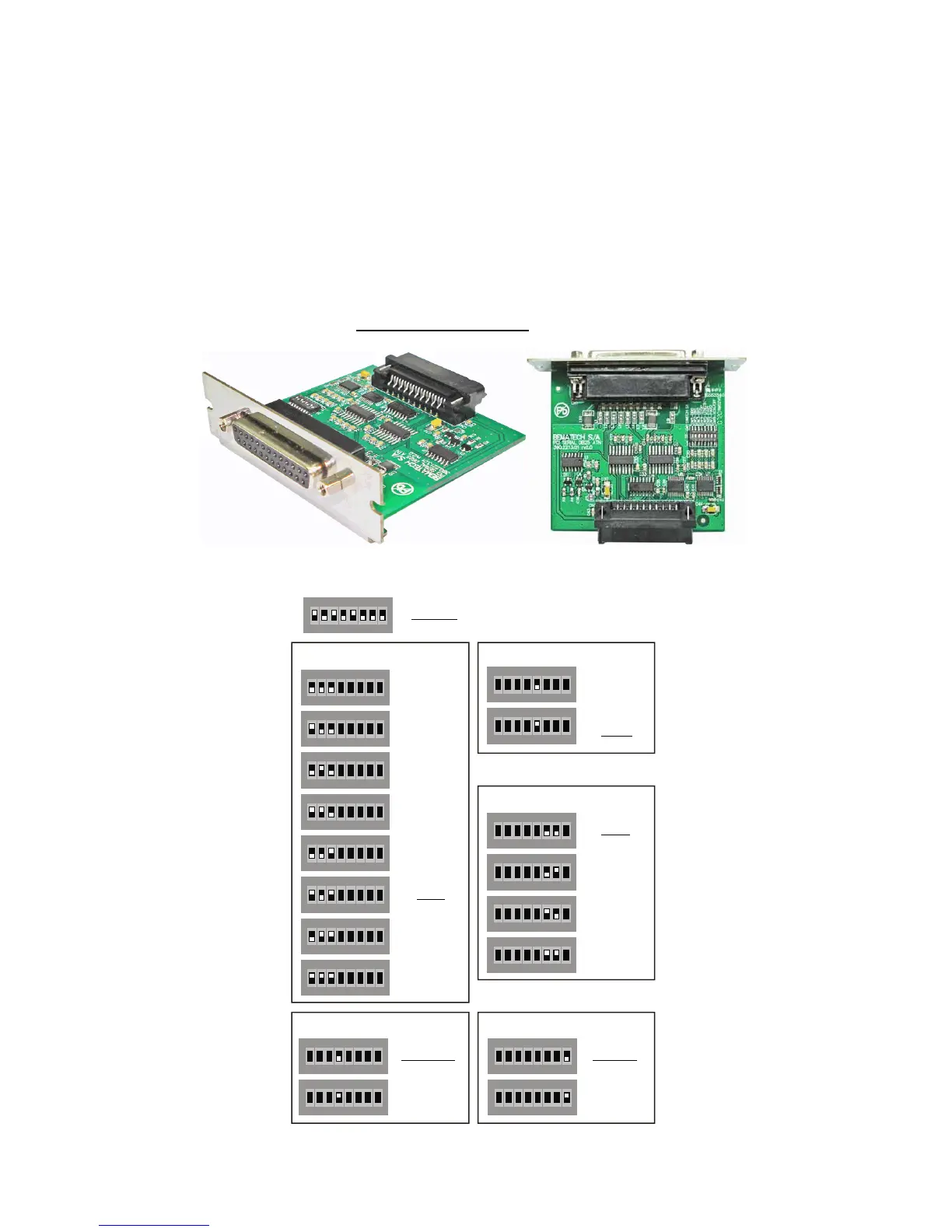
Serial Board DB-25
The ICs U2 and U3 (MAX3232) convert the levels originated from the microcontroller serial
interface, which are of 3,3V into signals of ±10V, compatible with RS232 standard and the
RS232 signals originated from the outside in 3,3V signals compatible with the microcontroller.
The available signs on the interface are RXD, TXD, RTS, CTS, DTR and DSR.
The recognition of the interface connected to the control board is made by the reading of a
code associated to each kind of board through the U6 enabled by the SELDEV signal generated
by the control board.
Jumpers JP2 and JP3, when closed, supply peripheral connected to the serial port with voltage
of +5V and 500mA current (must be closed only when needed).
On the S1 dip-switch, it is possible to adjust the serial communication configurations (stop
bits, parity, etc.). Below, there are some charts that contain the functions of each set of
switches. The configurations in Underlined-Bold face
are the factory default.
Dip Switch
1 2 3 4 5 6 7 8
ON DIP
1 2 3 4 5 6 7 8
ON DIP
1 2 3 4 5 6 7 8
ON DIP
1 2 3 4 5 6 7 8
ON DIP
1 2 3 4 5 6 7 8
ON DIP
1 2 3 4 5 6 7 8
ON DI