Summary
Introduction...........................................................................................................5
Who should read this manual?..................................................................................5
How this manual is organized...................................................................................5
Other related publications and software .....................................................................5
Where to find more information................................................................................5
Chapter 1 ............................................................................................. 6
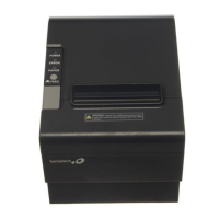
Product Description .................................................................................................6
Package contents....................................................................................................6
Chart of Models......................................................................................................7
Product electronics .................................................................................................7
Control Board......................................................................................................7
Connectors.......................................................................................................8
Jumpers...........................................................................................................8
Blocks Diagram.................................................................................................9
Parallel Interface Board ......................................................................................10
Block Diagram ................................................................................................10
Female Centronics Connector (Printer) ...............................................................11
Communication Cable......................................................................................11
Serial Interface Board DB-9.................................................................................12
Dip Switches .................................................................................................. 12
Block Diagram ................................................................................................13
Female DB-9 Connector (Printer).......................................................................13
Communication Cable......................................................................................13
Serial Board DB-25 ............................................................................................14
Dip Switch .....................................................................................................14
Block Diagram ................................................................................................15
Female DB-25 Connector (Printer).....................................................................15
Communication Cable......................................................................................15
USB Interface Board...........................................................................................16
Blocks Diagram...............................................................................................16
Female Type B Connector (Printer) ....................................................................16
Communication Cable......................................................................................16
Ethernet Interface Board.....................................................................................17
Block Diagram ................................................................................................17
Female RJ-45 Connector (Printer)......................................................................18
Communication Cable......................................................................................18
AC Adapter ....................................................................................................... 18
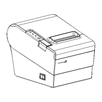
Product exploded view (with part numbers)..............................................................20
Product exploded view........................................................................................20
Exploded view of the Control Board Cartridge Set...................................................21
Exploded view of the Cabinet Set .........................................................................22
Exploded view of the Cover Lever Set ...................................................................23
Exploded view of the Thermal Print Head Set.........................................................23
Exploded view of the Connection Board Set ........................................................... 24
Exploded view of the Cutter Mechanism Set........................................................... 25