Installation, connection and commissioning
29
isoPV425_D00028_09_M_XXEN/05.2018
For details about the conductor cross sections required for wiring, refer to the
technical data on Page 58.
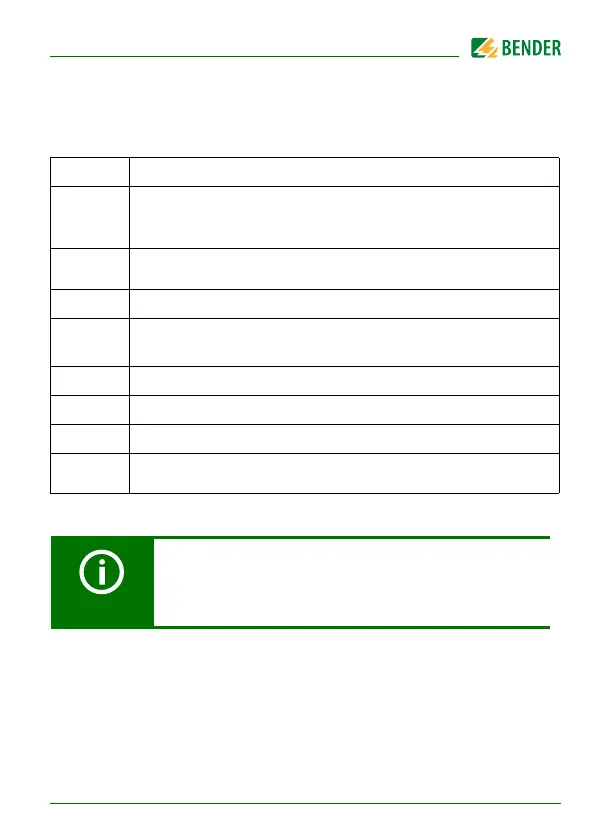
Wiring diagram legend:
Terminal Connections
A1, A2
Connection to the supply voltage U
s
via a fuse:
If supplied from an IT system, both lines have to be protected by a
fuse.*
E, E, KE
Connect each terminal separately to PE:
The same wire cross section as for "A1", "A2" is to be used.
L1/+, L2/– Connection to the 3(N)AC, AC or DC system to be monitored
Up, AK1,
GND, AK2
Connect the terminals of the AGH420 to the corresponding termi-
nals of the ISOMETER®.
T/R Connection for external combined test and reset button
11, 14
Connection to alarm relay "K1"
11, 24
Connection to alarm relay "K2"
A, B
RS-485 communication interface with selectable terminating resist-
ance
* For UL applications:
Only use 60/75°C copper lines!
UL and CSA applications require the supply voltage to be
protected via 5 A fuses.