23
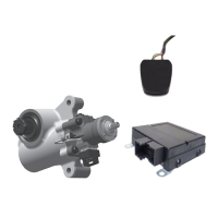
1. TheTABS-6AdvMCmoduleshallbeinstalledwiththe
followingconsiderations(seeFigures16through18):
5°
5°
VERTICAL
ORIENTATION
(ROLL ANGLE)
MUST BE
WITHIN FIVE
DEGREES OF
VERTICAL
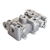
FIGURE 16 ‑ INSTALLATION ON TRAILER (VERTICAL)
10°
10°
Driving
Direction
Longitudinal
Orientation
(Pitch Angle)
Must be within
Ten Degrees of
Vertical
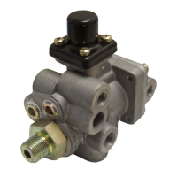
FIGURE 17 ‑ INSTALLATION ON TRAILER (LONGITUDINAL)
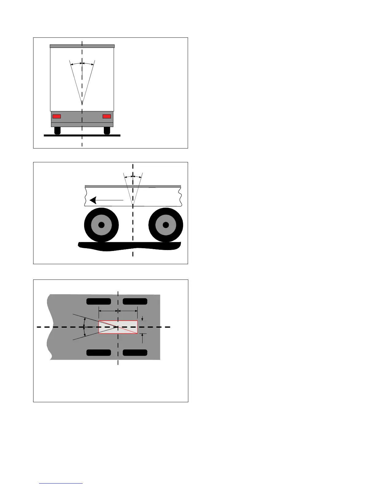
The TABS-6 Adv MC module must be located no
more than 40 inches from the mid-point between
the axles, and within two inches from the center
line of the trailer (unless congured for an offset).
10°
10°
± 40" (1 m) from mid-point between the axles
± 2" (5 cm)
from center
of trailer
FIGURE 18 ‑ INSTALLATION ON TRAILER (CENTER LINE)
• With exhaust port facing downward and unobstructed
withsignicantfreespacebelow(>1inch).
• Within±40"ofthecenteroftheaxle(s)forproper
balanced brake applications.
• Within±2"fromthecenterlineofthetrailer(default).
Note,aleft/rightoffsetgreaterthan±2"mayhave
beenprogrammedintheECUandcanbeveried
using Bendix ACom diagnostic software (version
6.1orhigher).
• Yaw angleshall be ± 10°as measured from the
center line of the trailer.
• Pitchangleshallbe±10°asmeasuredfromaat
horizontal plane.
• Roll angle shall be within ± 5° as measured from a
athorizontalplane.
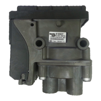
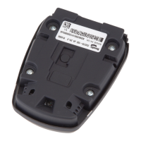
Frame‑mount module: The TABS‑6 Adv MC module
usesthreeClass8steelM10x1.5nutswithlockwashers,
torquedto354±44.4in.-lbs(40±5Nm).
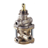
2. Reconnect all air hoses and plugs to the module.
Depending on the installation, additional plugs may
be necessary. Thread sealant products that contain
Teonmaybeused,howeverthreadsealanttapeisnot
recommended as there is a potential for tape material
entering the valve and affecting the valve’s operation.
Make certain that no thread sealant enters the valve.
Allairhosesandttingsshouldbecheckedforleaks
prior to returning the vehicle to service.
3. Reconnect the ECU power, auxiliary if present and
wheelspeedsensorelectricalconnectorstotheECU.
Apply a moderate amount of non‑conductive electrical
grease to each connector pin before reconnecting.
Note:Thewheelspeedsensorsmustfollowtheorienta‑
tionofthemoduleasshowninFigure19forxedaxle
trailers. Where a lift axle is present, and sensors are
tobeinstalledonthataxle,secondarysensorsSEand
SF must be used for the lift axle.
• Itisnecessarytoxthewheelspeedsensorsto
the orientation of the lateral acceleration sensor for
plausibility checks between the sensors.
• If the wheel sensor location does not match the
orientation of the Bendix
®
TABS‑6
™
Adv MC module
shown in Figure 19, a Diagnostic Trouble Code
(DTC)willbegeneratedandtheABSindicatorlamp
will be illuminated.
• Refer to the raised lettering on the top cover for
wheelspeeddesignation,“S-C”,“S-D”,“S-E”,and
“S‑F”.
4. Leakage and OperationalTests must be performed
before returning the vehicle to service.
LEAKAGE AND OPERATIONAL TESTS
1. Beforeperformingtheleakagetests,blockthewheels.
2. Fully charge the air brake system and verify proper
brake adjustment.
3. Makeseveraltrailerbrakeapplicationsandcheckfor
prompt application and release at each wheel.