8
CAUTION: Correct wheel speed sensor installation is
necessary for optimal ABS operation.
NOTE:Ifthetrailerisequippedwithaliftaxlethatwilluse
wheel speed sensors, it is important that secondary sensors
SEandSFbeusedforthisaxle.Seethesystemdiagrams
included in this document. In all cases, the primary wheel
speed sensors must be locatedon the xed axle. For
2S/2Msystems,thexedaxlesensorsareSCandSD.
1. ForincreasedcorrosionprotectionBendixrecommends
that a high‑temperature rated silicon‑ or lithium‑based
grease be applied to the interior of the mounting block,
the sensor, and to a new clamping sleeve.
2. Install the new clamping sleeve fully into the block,
with the retaining tabs toward the inside of the vehicle.
Please note that Bendix WS‑24 wheel speed sensors
must use the correct clamping sleeve to avoid problems
associated with reduced retention force, such as sensor
movement and resulting ABS trouble codes. See
Figure 4.
3. Gently push (DO NOT STRIKE) the sensor into the
mounting block hole until it bottoms out on the face of
the tone ring. Secure the cable lead wire to the knuckle/
axlehousing3-6inchesfromthesensor.
4. Apply a moderate amount of dielectric non‑conductive
grease to both the sensor and harness connectors.
5. Engagetheconnectors,andpushthemtogetheruntil
the lock tab snaps into place. It is permissible to use an
extrawireretainer(partnumber300122,orequivalent),
if available, to hold the connectors together.
ThefrictiontallowstheWS-24sensortoslidebackand
forth under force, but to retain its position when the force
is removed. When the WS‑24 sensor is inserted all the
way into the mounting block and the wheel is installed on
the axle, the hub exciter contacts the sensor, which pushes
the sensor back. Also, normal bearing play will “bump” the
sensor away from the exciter. The combination of these
two actions will establish a running clearance, or air gap,
between the sensor and exciter.
CAUTION: Wheel bearing maintenance is an important
part of keeping the wheel speed sensors in the correct
position. Excessive wheel end play can result in DTCs
in cases where the sensor is pushed too far away
from the tone ring for a good signal to be produced.
Maintain wheel bearings per the manufacturer's
recommendations.
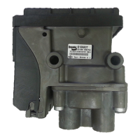
8. ABS INDICATOR LAMP
Trailer‑mounted Lamp
The Bendix
®
TABS‑6
™
Adv MC module controls an ABS
indicator lamp to show the trailer ABS status. With power
supplied by the towing vehicle — if there is an active
DiagnosticTroubleCode(DTC),orduringthebulbtestat
start‑up — the module illuminates the ABS indicator lamp
byprovidinga 12.0VDC signal.(The otherside ofthe
lamp is grounded.) The ABS indicator lamp output uses
pin 5 of the 7‑pin connector on the module.
Dash‑mounted Lamp (PLC Controlled)
TABS-6Adv MC modules use SAEJ2497 standards to
supportPower Line Carrier (PLC) communication. The
status of the trailer ABS is transmitted over the ignition
powerwire(thebluewireoftheJ560connector)—pin1
of the 7‑pin module connector.
IfthereisanactiveDTC,duringthebulbcheckatstart-up,
the TABS‑6 Adv MC module will transmit a signal over
thepowerlinetothetowingvehicle’sECU.Thetowing
vehicle’s ABS controller will then illuminate the trailer ABS
indicator lamp mounted on the dash.
9. BENDIX
®
WS‑24
™
WHEEL
SPEED SENSORS
See Figure 4. Wheel speed data is provided to the TABS‑6
Adv MC module by the Bendix
®
WS‑24
™
wheel speed
sensors. Typically, the WS‑24 wheel speed sensor is
installed in a mounting block that is welded to the axle
housing. The WS‑24 wheel speed sensors are protected
by a stainless steel sheath. They are designed to be
used with beryllium copper clamping sleeves (sometimes
referred to as a “retainer bushing”, “friction sleeve”, or “clip”)
(See Figure 4).Theclampingsleeveprovidesafrictiont
between the mounting block bore and the WS‑24 sensor.
Vehicles have an exciter ring (or “tone ring”) as part
of the wheel assembly. (The default setting expects a
100-toothtoneringtobeused.See Section 17 for more
information.) As the wheel turns, the teeth of the exciter
ring pass the wheel speed sensor, generating an AC signal
whichisdeliveredtotheTABS-6AdvMCmoduleECU.
Thesignalvariesinvoltageandfrequencyasthewheel
speed changes.
Vehicle axle andABS control congurations determine
if two, or four, wheel speedsensors are required. See
Figures 20 and 21 for an electrical system schematic
showing wheel speed sensor connector pin locations.