38
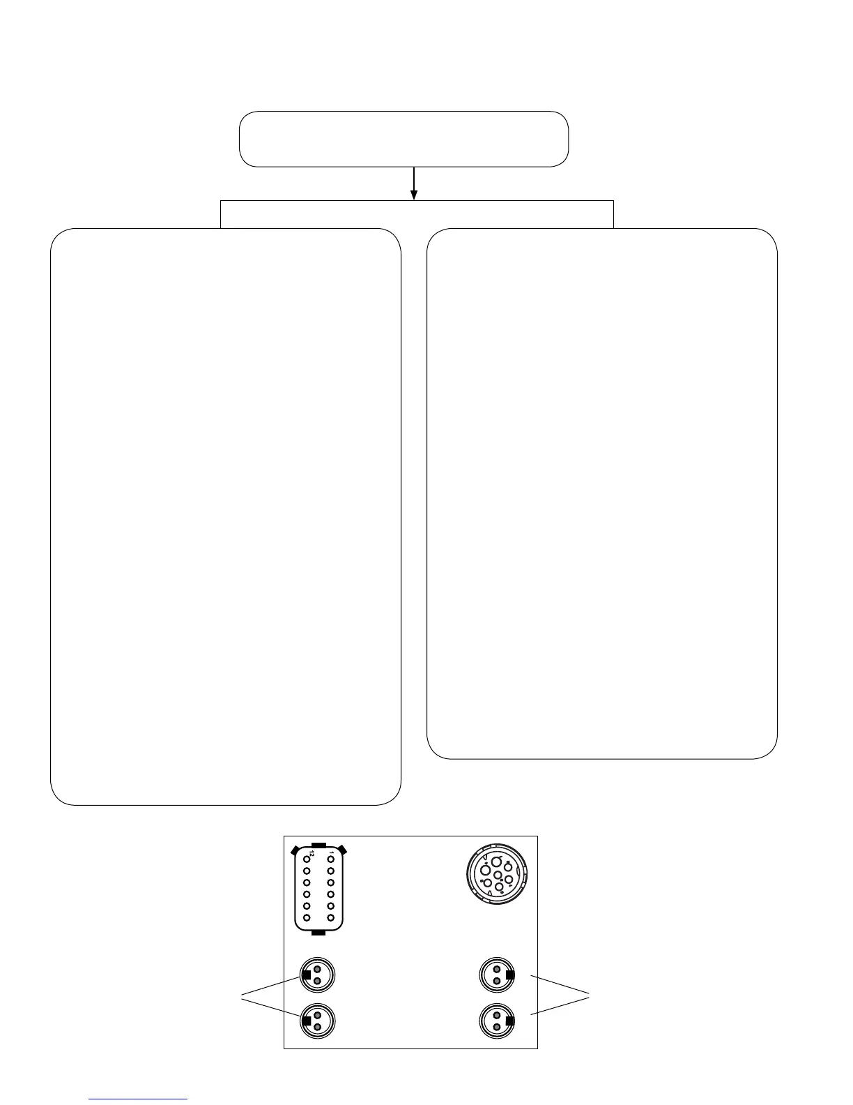
S‑D and S‑F Sensor
(SeeFigure19forUsage.)
S‑C and S‑E Sensor
(SeeFigure19forUsage.)
SECTION E: TROUBLESHOOTING THE
BENDIX
®
WS‑24
™
WHEEL SPEED SENSORS (WSS)
Turn off the power to the module, disconnect
the wheel speed sensor connector.
Note: Both Static and Dynamic WSS DTCs may be present:
S-F
S-E
S-D
S-C
If Dynamic WSS DTCs are present:
Rotate the affected wheel and verify a minimum
of0.25VACsensoroutput@0.5RPSacrossthe
wheel speed sensor pins. A properly positioned
sensorcanoutputmorethan2.0VAC@1RPS
Verify/inspect the following:
• Speed sensors properly contact the tone ring.
• The condition and retention force of the sensor
sleeve.
• Proper sensor lead condition, routing and
clamping sleeve.
• Condition of tone ring mounting and teeth.
• Proper number of tone ring teeth per sensed
wheel.
• Proper adjustment of wheel bearings.
• Condition of foundation brakes.
• Check for corroded/damaged wiring or
connectorsbetweentheECUandtheWSS.
Make repairs as needed (replace wiring and/or ABS
components).
ResetactiveDTC’sbyusinganyofthefollowing
methods:
• BlinkCodeDiagnostics,Section20,
• PCdiagnostics,Section23.
• BendixRemoteTrailerDiagnosticUnit(TRDU)
andmagnet,Section23.
• Bendix
®
TrailerInformationModule,Section23.
(If you do not reset manually, typically these will reset
automatically when the vehicle has been driven for a
period of time.)
Thenrerunthepowerupsequence.GotoSectionA.
If Static WSS DTCs are present:
Usingavolt/ohmmetertomeasuretheconnector
pinsofthesensorwithaDTC,verify950-1950
OHMSacrossthesensorconnectorpins.
Verify/inspect the following:
• Nocontinuityfromsensorconnectorpinsto
ground.
• Vbat not measured at either sensor connector
pins.
• Verify there is no continuity between the sensor
leads and other sensors.
• Sensor/ECUwiringandconnectorsarenot
damaged or corroded.
• Proper sensor wire routing and clamping.
Make repairs as needed (replace wiring and/or ABS
components).
ResetactiveDTC’sbyusinganyofthefollowing
methods:
• BlinkCodeDiagnostics,Section20,
• PCdiagnostics,Section23.
• BendixRemoteTrailerDiagnosticUnit(TRDU)
andmagnet,Section23.
• Bendix
®
TrailerInformationModule,Section23.
ThencheckforDynamicWSSDTCs,seeleft
column.
Thenrerunthepowerupsequence.GotoSectionA.