36
SECTION C: TROUBLESHOOTING THE TRAILER‑MOUNTED
ABS INDICATOR LAMP CIRCUITRY
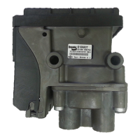
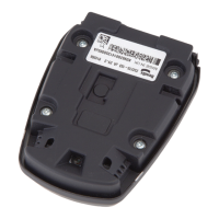
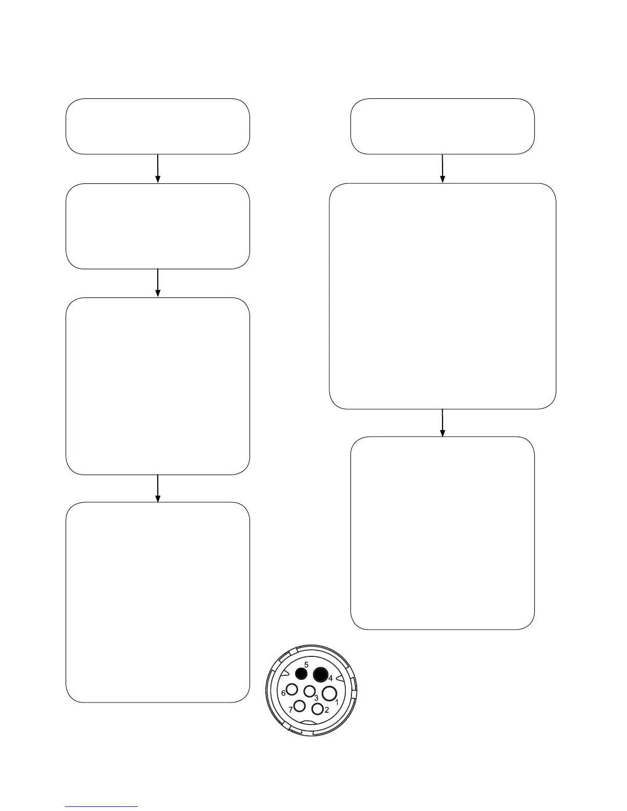
LookingintotheBendix
®
TABS‑6
™
Adv MC
Module 7‑pin Connector Pigtail Harness.
Pin 4 is the ground pin.
Pin 5 is the ABS indicator lamp pin.
The trailer‑mounted ABS indicator
lamp did not illuminate during the
power-upsequence.
The trailer‑mounted ABS indicator
lampremains“ON”duringthepower-
upsequence.
Troubleshoot the power supply
to the ABS module.
GotoSectionD.
Continue if the power and ground
wiringareOK.
Turn off the power to the module.
Inspect the condition of the ABS
indicator lamp, connector and ground.
Using a volt/ohm meter, verify
continuity from the trailer chassis
ground (pin 4) to the ground pin of
the indicator lamp.
If repairs are made, rerun the
power-upsequence.Goto
Section A.
Continue if the indicator lamp and
groundwirecheckoutOK.
DetermineifamoduleDiagnosticTrouble
Code(DTC)existsusinganyofthefollowing
methods:
• Blinkcodediagnostics,Section20,
• PCdiagnostics,Section23,
• TrailerRemoteDiagnosticUnit,
Section23,or
• Bendix
®
Trailer Information Module, also
Section23.
IfDTC(s)exist,andrepairsaremade,rerun
thepower-upsequence.GotoSectionA.
ContinueifnoDTCsarefoundandtheABS
module appears to be functioning normally.
With power off to the ABS
module,disconnectthe7-pinECU
connector.
Verify continuity from the ABS
indicator lamp pin (pin 5) of the
ECUconnectortotheABSindicator
lamp connector.
If repairs are made, rerun the
power-upsequence.Goto
Section A.
If the condition persists, replace the
ABS module.
With power off to the ABS
module,disconnectthe7-pinECU
connector.
Usingavoltmeter,verifythatthere
is not a short to the Vbat between
theABSWLpinoftheECU
connector and the ABS indicator
lamp connector.
If repairs are made, rerun the
power-upsequence.Goto
Section A.
If the condition persists, replace the
ABS module.