24
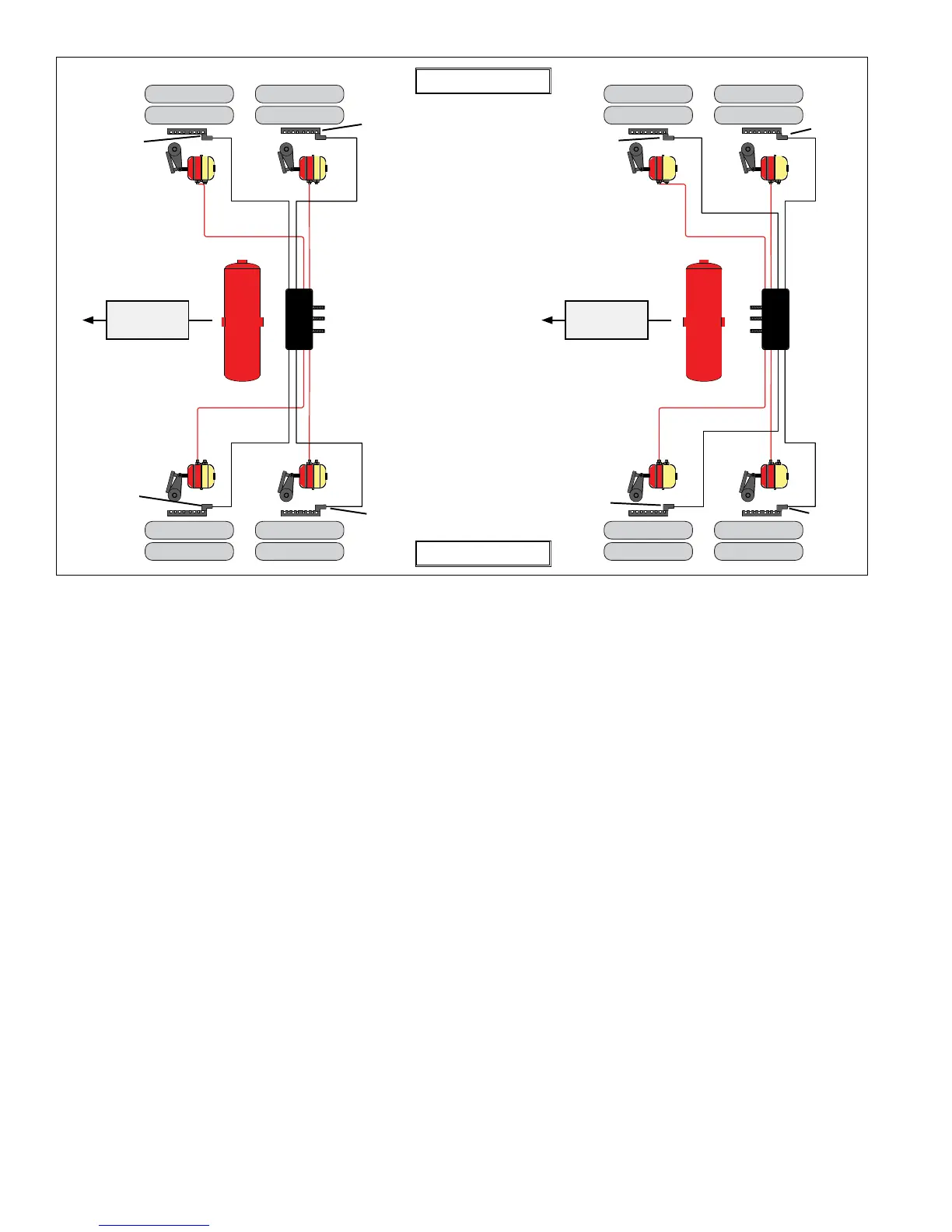
FIGURE 19 ‑ WHEEL SPEED SENSOR INSTALLATION
P22
P21
P21
P22
0° Mounting Orientation 180° Mounting Orientation
Vehicle Driving
Direction
Vehicle Driving
Direction
Right - “Curb Side”
Left - “Road Side”
Sensor
“S-F”
Sensor
“S-D”
Sensor
“S-C”
Sensor
“S-E”
Sensor
“S-E”
Sensor
“S-D”
Sensor
“S-F”
Sensor
“S-C”
4. Check the TABS‑6 Adv MC module, modulator valve(s)
and all air hose fittings for leakage using a soap
solution.
Check the ABS solenoid body with the trailer service
brakes fully applied. If leakage is excessive — more
thanasingle1"bubblewithin1minute—replacethe
TABS‑6 Adv MC module.
Check the relay exhaust port with the trailer service
brakes released to be sure that leakage is less than
a single 1" bubble within 3 seconds. If excessive
leakage is detected at the relay exhaust port, perform
the following test before replacing the TABS‑6 Adv MC
module:
• Apply the trailer spring brakes. Recheck for leakage
around the relay exhaust port. If the exhaust port
stops leaking, this indicates a leak between the
emergency and service sides of the spring brake
chamber. However, if the relay exhaust port
continues to leak excessively, replace the TABS‑6
Adv MC module.
5. Applypowerand monitorthe power-upsequence to
verify proper system operation. See Section 15.
6. Calibrate and set odometer parameters, if necessary,
using a diagnostic tool. See Section 16.
7. Perform an installation test using a diagnostic tool.
Minimum teststhat are required to verify the proper
installation of the ABS/TRSP system are:
• ECU Information: This test provides the user with
specic ECU information. It is required that no
DTC’s(otherthan“end-of-linetestnotcompleted”)
arepresentandthattheECUhasbeencongured.
• Wheel End Sequence Test: During thistest,
checks are carried out that verify the correlation of
the wheel installed with a Wheel Speed Sensor and
the Pressure Modulator that controls the pressure
to the associated brake.
• Lateral Acceleration Test: The installation angle
informationisretrievedfromtheECUandcompared
tothepredenedlimits(+/-5 degrees).Thistest
veriesthattheunitisinstalledasclosetohorizontal
as possible.
• Pressure Sensor Test: Duringthistest,checksare
carried out that verify that the proper response is
received from the pressure sensors during a brake
application.
• Axle Load Sensing Test (Air Ride): The test
has the user verify the expected measurement
of the load pressure sensor, Port 42, for air ride
suspensions. The program provides the reading
of the sensor.