5
5. COMPONENTS
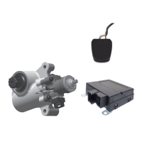
Installations of the TABS‑6 Adv MC module use the
following components:
Internal:
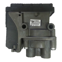
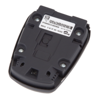
• Electronic Control Unit (ECU): TheECUmonitors
the speed sensor signals, lateral accelerometer sensor
signalandvariouspressuresensors(andifcongured,
externalspringdeectionsensor)todeterminewhen
ABS and/or TRSP intervention is required. When
needed, the ECU actuates the appropriate pressure
modulator valves to optimize the brake pressure. The
ECUmonitorsthesystemtodetectandwarnthedriver
ofanymalfunctions.DiagnosticTroubleCodes(DTCs)
arestoredintheECUandcanbereviewedtodiagnose
the TABS‑6 Adv MC module system.
• Lateral Accelerometer Sensor: The lateral accel‑
erometer sensor senses the lateral movement of the
trailer and sends an electrical signal directly propor‑
tionaltothetrailer’slateralaccelerationtotheECU.
• Supply Pressure Sensor: (non‑serviceable, and
located within the module.)
• Internal Load Sensor:
For air suspension systems, the load sensor port (P42)
mustbeplumbedtoaxedaxleairridebellows.Note:
the sensor must not be plumbed to a lift axle bellows
since they are not charged when the axle is not
being used. The function of this sensor is to monitor
the pressure and send an electrical signal directly
proportionaltothetrailer’saxleloadtotheECU.
• Brake Demand Pressure Sensor: This sensor
monitors the trailer service brake pressure being
applied by the driver and sends an electrical signal
directly proportional to the driver’s brake demand to
theECU.
• Brake Delivery Pressure Sensors: These sensors
(P21,P22)monitorthetrailerservicebrakepressure
that is being delivered to the wheel ends through, or
by, the TABS‑6 Adv MC module system and sends
electrical signals directly proportional to the delivered
trailerservicebrakepressuretotheECU.
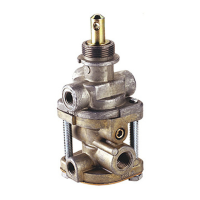
• Modulator Relay Valve (MRV): MRVs are integrated
into the module and are controlled electrically by the
ECUtodecrease,hold,orallowthefullappliedbrake
pressure into the brake chamber to control the braking
torqueatthewheels.
External:
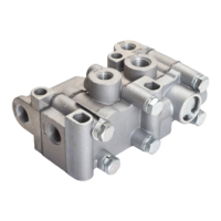
• Wheel Speed Sensors (WSS):Locatedatselected
hubs, wheel speed sensors detect the rotation of indi‑
vidualwheelsandsendanelectricalsignaltotheECU
proportional to the rotational velocity. See Figure 3.
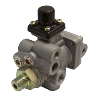
• External Load Sensor:
For spring suspension systems, an external electrical
springdeectionsensorisinstalled—typicallyasclose
to the center (±5 inches) as possible of an axle with
linkage attached to the center of the axle (but MUST
NOT be installed on a lift axle), See Figure 4. Vehicles
with a mechanical load sensor have the port (P42) used
for sensing the air suspension system plugged.
Note: Do Not Use
Previous WSS
Clamping Sleeves
That Have “BW”
in a Diamond
90° Speed
Sensors
Straight Speed
Sensors
Sensor
Clamping
Sleeve
Acceptable
Logo-Stamped
Sleeves
FIGURE 3 ‑ BENDIX
®
WS-24
™
WHEEL SPEED SENSORS
Load Sensor
Vertical Linkage Rod
Axle Attachment
Bracket
Axle Strap-Style
Fastener Clamp
Mounting
Bolts
Rubber
Link and
Rod
Adjustable Linkage
with Rubber Link
FIGURE 4
‑ TYPICAL
EXTERNAL
LOAD SENSOR
INSTALL ATION
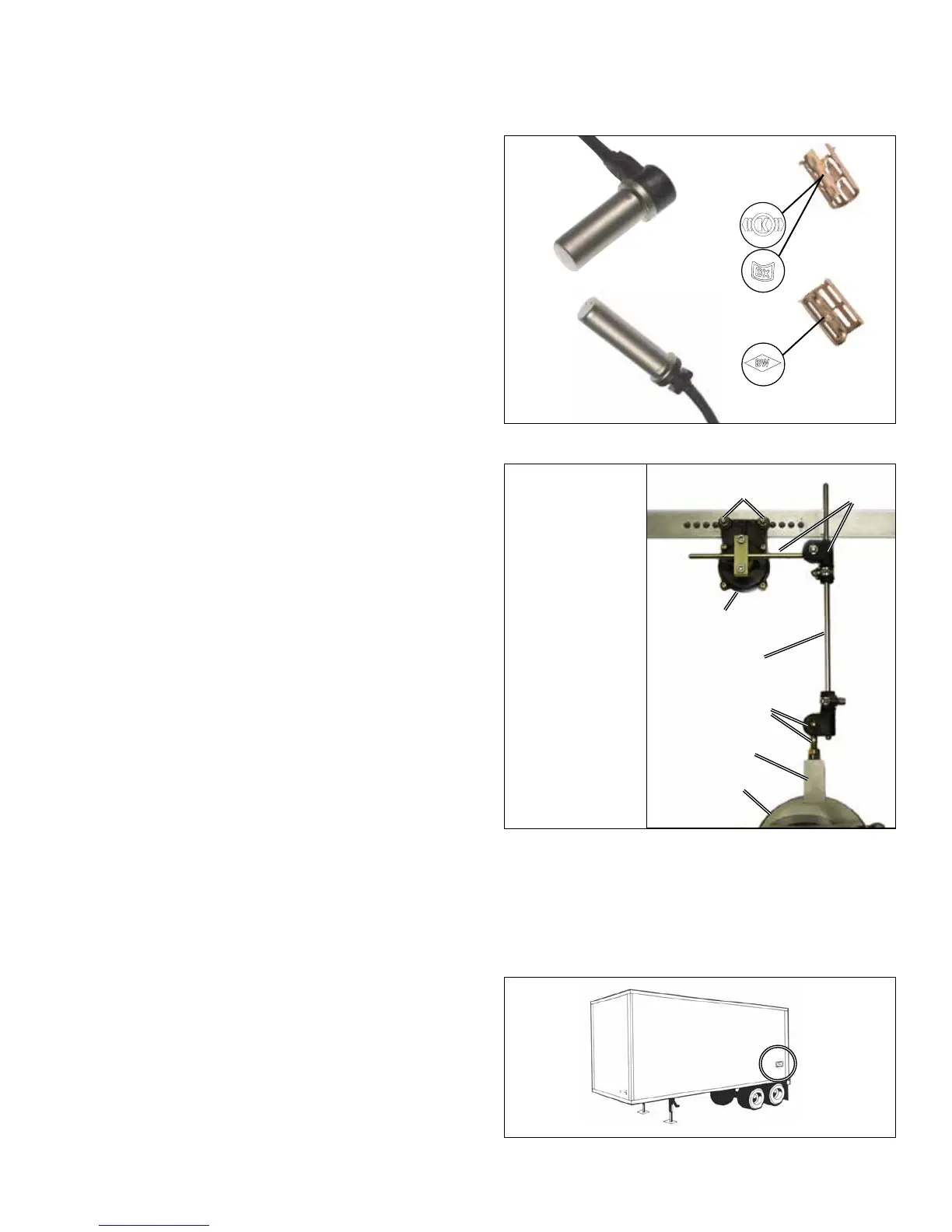
• Trailer ABS Indicator Lamp: ControlledbytheECU
to show the ABS status, the trailer ABS indicator lamp
illuminateswhenaDiagnosticTroubleCode(DTC)is
active. See Figure 5. If there are no ABS diagnostic
trouble codes present, when ignition power is applied
totheECU,thelampwillilluminateasabulbcheck
lasting typically two (2), up to six (6) seconds at most.
FIGURE 5 ‑ TRAILER-MOUNTED ABS INDICATOR LAMP