EasyManua.ls Logo

BENDIX TABS-6 User Manual

BENDIX TABS-6
40 pages
To Next Page IconTo Next Page
Page #1 background imageLoading...
Page #1 background image
1
Bendix
®
TABS‑6
Advanced Multi‑Channel Trailer ABS Module
FIGURE 1 - BENDIX
®
TABS -6
ADVANCED MULTI-CHANNEL MODULE (BENDIX TABS-6 ADV MC)
1. INTRODUCTION
The Bendix
®
TABS‑6
Adv MC module is an integrated multi‑
channel (4S/2M) trailer service brake module controller for
air‑braked heavy‑duty semi‑trailers that features Bendix
®
Antilock Brake System (ABS) and Bendix
®
Trailer Roll Stability
Program (TRSP
®
).
Installed on semi‑trailers, the module acts as a relay valve
during normal braking, but during ABS events it will intervene
to help maintain vehicle stability and minimize stopping
distance by preventing wheel lock‑up. The Bendix TRSP
monitors the trailer's motion and reduces the risk of roll overs
by automatically applying the brakes when a risk of roll over
is detected.
This module features:
● AmodulardesignwithanintegratedElectronicControlUnit
(ECU);pressuresensors;alateralaccelerationsensor;and
Modulator Relay Valves (MRVs) — eliminating external
pigtail harnesses for these components.
● Anoperatingvoltagerangeof8-32volts.
● Anelectronicodometerwithtripcounters&serviceinterval
options.
● A scratch-pad feature with up to 1,008 bytes of freely
denableread/writetextspaceavailableforcustomeruse.
● Anextendeddataloggingfeature,includingaresettable
drive recorder.
Section TABLE OF CONTENTS ...........PAGE
1. Introduction ...........................1-2
2. Safe Maintenance Practices ................2
3. AntilockBrakeSystem(ABS)Operation .......3
4. TrailerRollStabilityProgram(TRSP)Operation 4
5. Components ..........................5‑6
6. Mounting ...............................7
7. Pigtail Wiring Harnesses . . . . . . . . . . . . . . . . . . .7
8. ABSIndicatorLamp.......................8
9. Bendix
®
WS‑24
Wheel Speed Sensors .......8
10. SAEJ2497(PLC)DiagnosticLink ...........9
11. SAEJ1939(CAN)DiagnosticLink ...........9
12. AuxiliaryI/O .............................9
13. Bendix
®
ABS Flex
Program ...............10
14. CustomerScratchPad....................10
15. Power-UpSequence . . . . . . . . . . . . . . . . . . . . .10
16. OdometerFunction ......................10
17. Non-StandardTireSize ...................11
18. DiagnosticTroubleCodeDetection ..........11
19. PartialABSShutdown . . . . . . . . . . . . . . . . . . . . 11
20. BlinkCodeDiagnostics ................ 11-12
21. AuxiliaryFeatures .......................12
22. DiagnosticTroubleCodes(DTCs)........13-19
Troubleshooting Section...................20-40
Mounting Studs Mounting Studs
ECU Cover
(Sealed)
ECU Connector Covers
on Both Sides
(Removable)
Cover Lock
with Slide Lock
Tab
12-Pin Connector
7-Pin
Connector
SD‑13‑47672
Wheel Speed
Sensor
Connectors
Wheel Speed
Sensor
Connectors
For Port
Descriptions
See Page 3
For Part Label Information
See Page 40
Part Number
Etched Here

Table of Contents

Questions and Answers:

BENDIX TABS-6 Specifications

General IconGeneral
TypeTrailer ABS Module
Operating Temperature Range-40°C to +85°C
Protection RatingIP67
CategoryAutomobile Accessories
Voltage12V/24V
CommunicationJ1587/J1939
MountingFrame Mount
ManufacturerBENDIX
System TypeABS
Number of Channels4S/2M

Summary

Introduction to Bendix TABS-6 Adv MC Module

Module Overview and Key Features

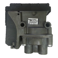
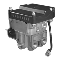
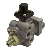
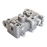
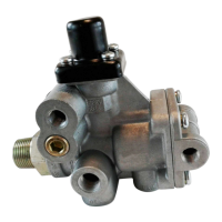
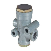
Overview of the integrated multi-channel trailer ABS module and its features.

Safe Maintenance Practices and Precautions

General Safety Guidelines

Essential safety precautions for working on or around the vehicle.

Component Handling and System Integrity

Procedures for handling components and ensuring system integrity.

Antilock Brake System (ABS) Operation

ABS Operation Modes (Normal, Side, Axle)

Describes normal braking, side control, and axle control intervention.

ABS Fail-Safe Behavior

Explains the system's fail-safe behavior in case of malfunctions.

Trailer Roll Stability Program (TRSP) Operation

TRSP Purpose, Warnings, and Sensors

Explains TRSP's role in preventing rollovers and lists its sensors.

TRSP Intervention with Driver Actions

Details how TRSP intervenes and interacts with driver actions.

TABS-6 Adv MC Module Components

Internal and External Components

Lists and describes internal and external parts like ECU, sensors, and MRVs.

Indicator Lamp and Connector Details

Covers the trailer ABS indicator lamp and connector types.

Wiring Harnesses and Axle Sensing Features

Pigtail Harnesses and Lift Axle Sensing

Details pigtail harnesses and lift axle sensing functions.

Load Sensor Functionality

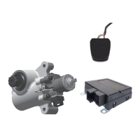
Explains the load sensor's role and connection for load monitoring.

Module Mounting and Electrical Connections

Frame Mounting Specifications

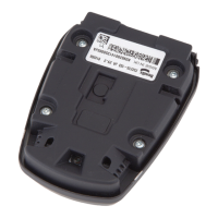
Covers the specifications for mounting the module to the trailer frame.

Power, Ground, and Connector Details

Details power supply, ground connections, and connector types.

ABS Indicators and Wheel Speed Sensors

ABS Indicator Lamp Operation

Describes trailer-mounted and dash-mounted ABS indicator lamps.

Bendix WS-24 Wheel Speed Sensor Installation

Details installation and function of WS-24 wheel speed sensors.

Diagnostic Communication Protocols

SAE J2497 PLC and J1939 CAN Links

Information on PLC and CAN communication for diagnostics.

Auxiliary I/O Functions

Explains the module's auxiliary input/output capabilities.

Advanced Module Features

Bendix ABS Flex Program

Customization of auxiliary functions via ABS Flex program.

Customer Scratch Pad, Power-Up, and Odometer

Features for user data storage, self-checks, and mileage tracking.

Diagnostics and Diagnostic Trouble Codes (DTCs)

Non-Standard Tire Size and DTC Detection

Adjusting parameters for tire size and detecting DTCs.

Partial Shutdown and Blink Code Diagnostics

Explains system shutdown on DTCs and blink code diagnostics.

Auxiliary Features and Blink Code Operations

Suspension Dump, Lift Axle Control, and Blink Codes

Features for suspension, lift axle control, and blink code displays.

Diagnostic Trouble Codes (DTCs) - Reference

DTCs for Wheel Speed Sensors

Lists DTCs related to wheel speed sensor issues.

DTCs for Tire Diameter and Range

Codes for incorrect tire diameter or range settings.

Diagnostic Trouble Codes (DTCs) - Reference (Continued)

DTCs for Trailer Power and Pressure Sensors

Codes for power supply issues and internal pressure sensor faults.

DTCs for Lateral Acceleration Sensor

DTCs related to the lateral acceleration sensor.

Diagnostic Trouble Codes (DTCs) - Reference (Continued)

DTCs for Lateral Acceleration Sensor Signal

Further DTCs for lateral acceleration sensor signal issues.

Diagnostic Trouble Codes (DTCs) - Reference (Continued)

DTCs for Trailer System Braking

Codes related to trailer system braking plausibility.

Diagnostic Trouble Codes (DTCs) - Reference (Continued)

DTCs for TABS-6 Adv MC Module Errors

DTCs indicating internal module errors or configuration issues.

Diagnostic Trouble Codes (DTCs) - Reference (Continued)

DTCs for Auxiliary I/O Errors

Codes for errors in auxiliary input/output functions.

Diagnostic Trouble Codes (DTCs) - Reference (Continued)

DTCs for Auxiliary, Misc, and Load Sensor

Codes for auxiliary features, general issues, and load sensor errors.

Diagnostic Tools and Software

Bendix ACom Diagnostic Software

PC-based software for comprehensive diagnostics and configuration.

Bendix TRDU Tool

Hand-held tool for visual ABS DTC indication and troubleshooting.

Diagnostic Tool Operation and Support

TRDU Tool Operation and Reset Function

How to operate the TRDU tool and reset DTCs.

Bendix Trailer Information Module

Display device for system diagnostics and trailer data.

Module Servicing and Installation

Servicing, Removing, and Reinstalling the Module

Procedures for servicing, removing, and reinstalling the module.

Control Port Filter Maintenance and Reinstallation

Maintenance of the control port filter and reinstallation guidelines.

Module Installation and Testing Procedures

Installation Considerations and Mounting

Guidelines for correct module installation angles and mounting.

Reconnecting Components and Leakage Tests

Steps for reconnecting components and performing leakage tests.

Installation Test Procedures

System Checks and Test Requirements

Overview of mandatory tests for ABS/TRSP system installation.

Specific Installation Test Descriptions

Details on ECU info, wheel end, lateral acceleration, and pressure tests.

Final Checks and ABS Wiring

Road Testing and Safe Operation

Procedures for road testing ABS function and safe operation.

ABS Wiring Troubleshooting Guidelines

General guidelines for troubleshooting ABS wiring and connectors.

Troubleshooting Flowcharts - Overview

Using Blink Codes and Diagnostic Tools

How to retrieve DTCs and use troubleshooting flowcharts.

Power-Up Sequence Flowchart

Flowchart for diagnosing trailer-mounted ABS indicator lamp at power-up.

Troubleshooting Flowcharts - Dash Indicator Lamp

Dash-Mounted ABS Indicator Lamp Diagnosis

Flowchart for diagnosing the dash-mounted trailer ABS indicator lamp.

Troubleshooting Flowcharts - Indicator Lamp Circuit

Trailer-Mounted Indicator Lamp Circuitry

Steps to troubleshoot the trailer-mounted ABS indicator lamp circuit.

Troubleshooting Flowcharts - Power Supply

Power Supply Troubleshooting

Diagnosing issues with the module's power and ground supply.

Troubleshooting Flowcharts - Wheel Speed Sensors

Wheel Speed Sensor (WSS) Troubleshooting

Diagnosing dynamic and static DTCs for wheel speed sensors.

Troubleshooting Flowcharts - Load Sensor

Load Sensor (Out-of-Range) Troubleshooting

Diagnosing load sensor issues for spring and air suspension systems.

Electrical Schematics - Module Configurations

2S/2M and 4S/2M Module Schematics

Wiring diagrams for 2S/2M and 4S/2M module configurations.

Electrical Schematics - 2S/2M Side Control

2S/2M Side Control (0 & 180 Degree Mounting)

Schematics for 2S/2M side control with both mounting orientations.

Electrical Schematics - 4S/2M Side Control

4S/2M Side Control (0 & 180 Degree Mounting)

Schematics for 4S/2M side control with both mounting orientations.

Electrical Schematics - 4S/2M Axle Control

4S/2M Axle Control (0 & 180 Degree Mounting)

Schematics for 4S/2M axle control with both mounting orientations.

Electrical Schematics - 4S/2M Side Control with Lift Axles

4S/2M Side Control (Lift Axle, 0 & 180 Degree)

Schematics for 4S/2M side control with lift axles, both orientations.

Electrical Schematics - 4S/2M Axle Control with Lift Axles

4S/2M Axle Control (Lift Axle, 0 & 180 Degree)

Schematics for 4S/2M axle control with lift axles, both orientations.

Related product manuals