HD-973P Series Multi-Level Parking Lift 49 P/N 5900076 — Rev. B3 — January 2024
To install the Hydraulic Hoses:
Clean the Hydraulic Components using the information in Hydraulic Fluid Contamination.
Pick a Platform to begin with, then find the appropriate Hose length and a Hydraulic Elbow Fitting.
Take the Curved end of the Hydraulic Hose and, starting at the Hydraulic Cylinder, route the
curved end through the Retaining Rings and the Flex Tube opening.
When you are done, the curved end should be coming out of the Flex Tube opening near the
Power Unit.
On the Hydraulic Cylinder, remove the Shipping Plug from the connector at the Piston Rod end.
Attach the NPT connector on the JIC x NPT Elbow Fitting to the connector on the Hydraulic
Cylinder.
Attach the Straight end of the Hydraulic Hose to the JIC connector of the same Fitting.
Leave the Curved End of the Hydraulic Hose coming out of the Flex Tube opening; do not connect
it to the Power Unit at this point.
Repeat Steps 2 through 7 for the other Platform.
After all connections have been made, make sure all connections are securely tightened.
Note: The JIC x NPT Nipple Fittings and NPT x ORB Nipple Fitting will be connected to the Power
Unit later in the installation.
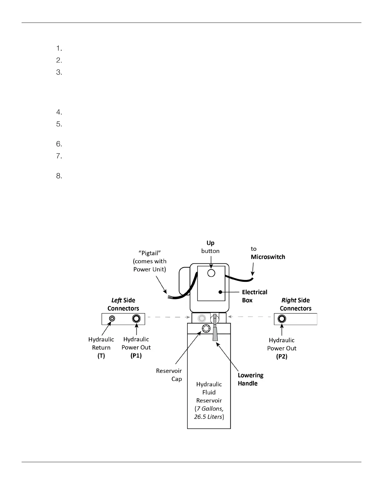
The figure below details the configuration for the Power Unit. P1/P2 represents the Hydraulic Power
Output Port; T1/T2 or CV1/CV2 commonly represents the Hydraulic Return Port.
Depending on your Power Unit, the connector locations may be different. Use the drawing below to
identify your layout and then attach your Hydraulic Hoses and Return Line appropriately.