10
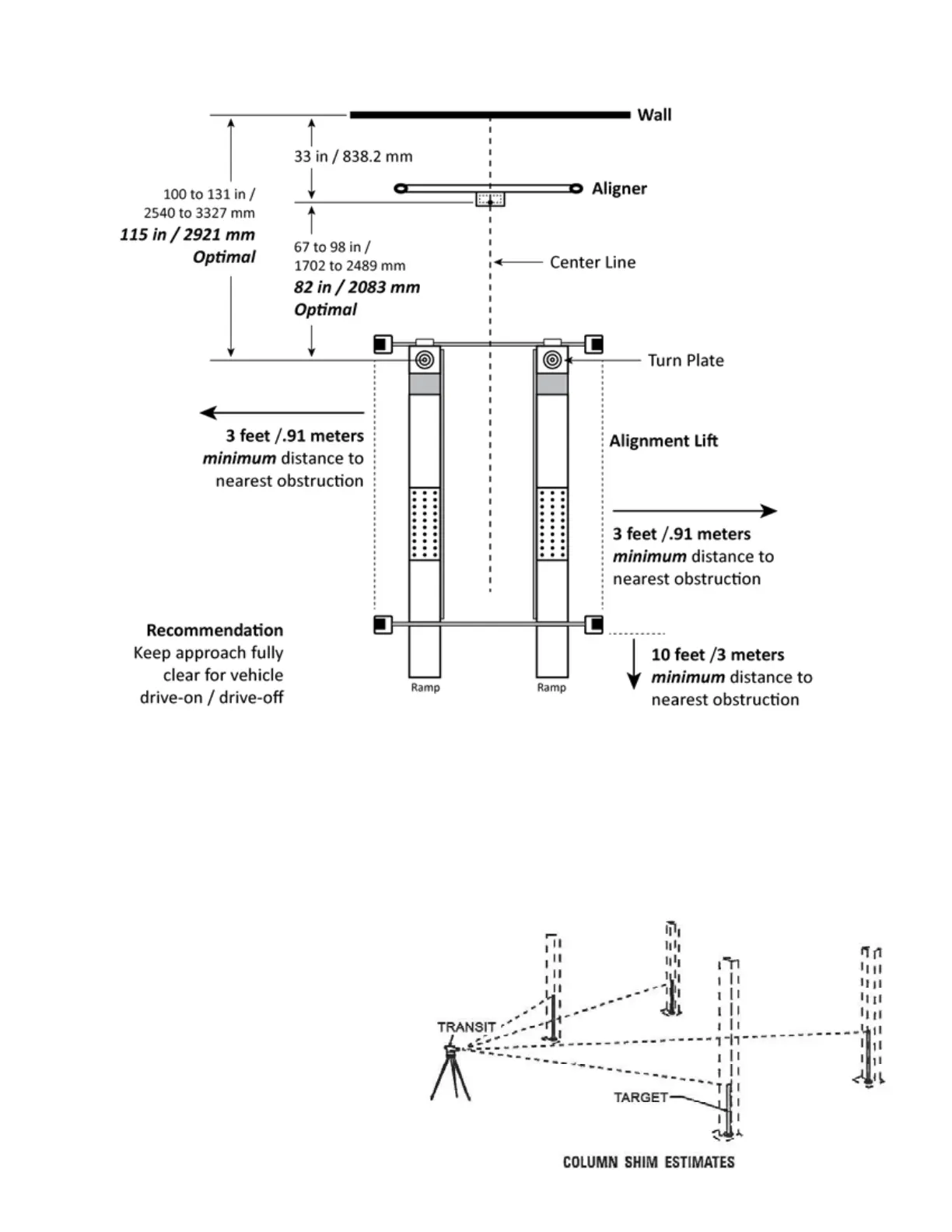
CLEARANCES
1. Lift Location: Use architects plan and Engineers
automatic level (transit) when available to locate lift. The
above shows clearances of a typical bay layout. Lift oor
area should be level.
2. Ceiling or overhead clearance must be 80” plus height
of tallest vehicle.
3. Estimating Column Shim requirements:
In the following section, the terms “highest” and “low-
est” refer to elevation of oor.
A. Mark locations where lift columns will be posi-
tioned in bay.
B. Place target on oor at column positions (NOT
on column base plates) and record readings.
C. Find the highest of the four locations. Find the
dierence between the readings at each of the re-
maining three columns and the highest reading.
D. The dierence is the estimated amount of shim
thickness needed at each column.
Note: Maximum shim thickness is 1/2” per column using
shims and anchors provided with lift.
If no transit is available, oor slope can be determined by
using a chalk line and level.