20
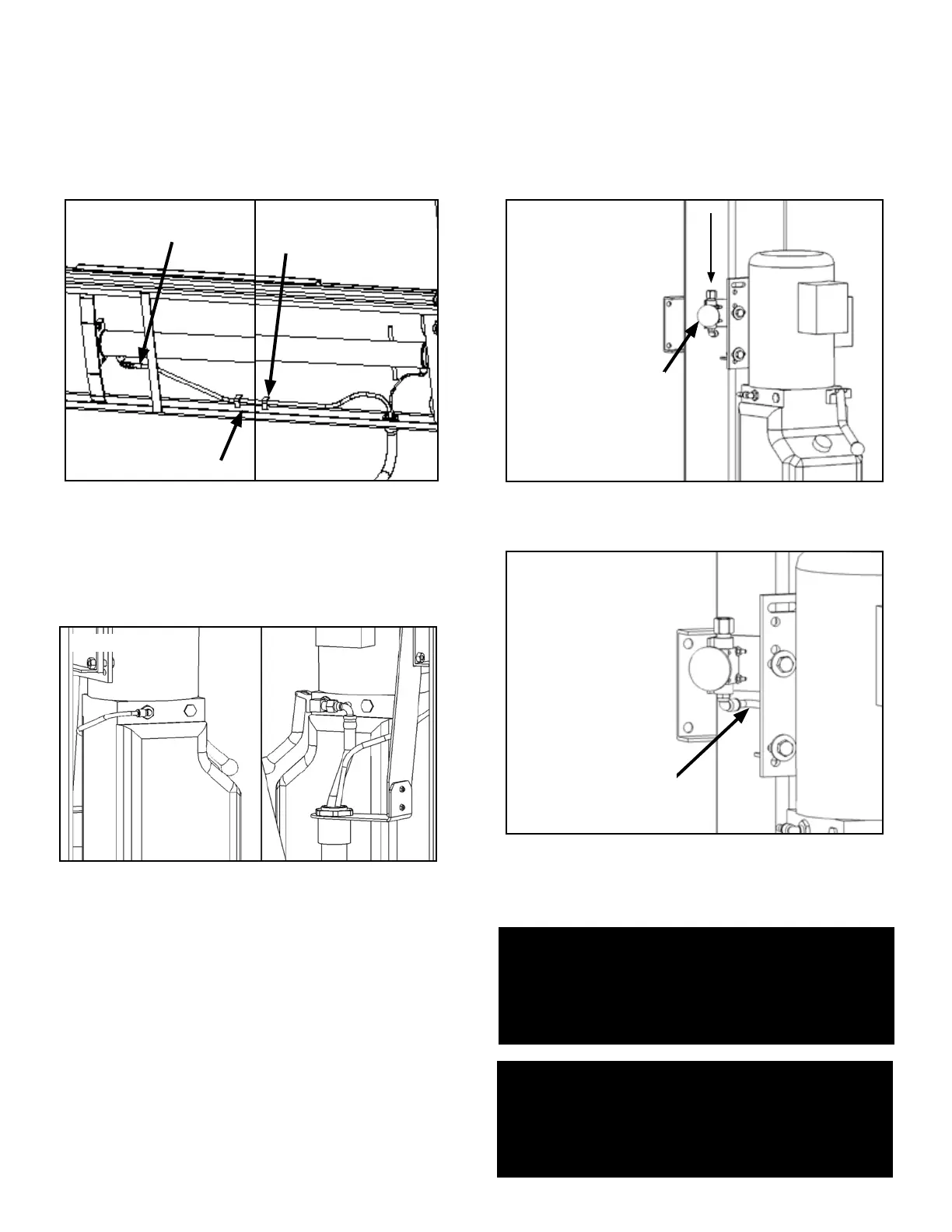
7. Connect the hydraulic hose and air line as shown
below making sure the hydraulic hose passes through the
retaining rings. MAKE SURE HOSES ARE KEPT CLEAR OF
CABLES. There will be one air line hose left unconnected in
this step. This air line will be used to activate the pneumatic
safety locks in the next step. See page 19 for Compression
Fitting instructions. (See Fig. 9.8)
8. Connect the straight end of the Power Unit Hydraulic
Line to the 90° Power Unit Fitting. Connect the Return Air
Line to the 90° Air Fitting. There will be one air line hose
left unconnected at this time. This air line hose will be used
to activate the pneumatic safety locks on the next page.
(See Fig. 9.9)
STEP 10
(Routing Air Lines)
1. Mount the Push Button Air Valve Assembly on to the
power unit mounting bracket. The Push Button Air Valve
should be positioned away from the Power Side Ramp on
the “out” side of the lift for operator safety. (See Fig 10.1)
2. Route the air line that was left unconnected in Step 9
to the 90° Air Line Compression Fitting of the Push Button
Air Valve Assembly. (See Fig 10.2)
3. Once the air line has been connected with the Push
Button Air Valve, cut the air lines to length by following
the Safety Air Line Routing diagram located on Page 20
and connect female branch “tee” fittings where needed.
Fig. 9.7
Retaining Ring
Retaining Ring
Straight Hose End
Fig. 9.8
Fig. 10.1
Air Supply In
Fig. 10.2
NOTE:
A FILTER/REGULATOR/LUBRICATOR MUST BE
INSTALLED ON AIR SUPPLY AT LIFT. FAILURE TO DO
SO WILL VOID THE WARRANTY.
NOTE:
MAKE SURE THE PUSH BUTTON AIR VALVE PORT
MARKED “INLET” IS FACING TOWARDS THE SOURCE
OF COMPRESSED AIR.
Push Button
Air Valve
Assembly
To Flex Hose