12
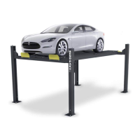
5. Install an M16 jam nut on to ladder bolt prior to the
installation of the Top Plate weldment. (See Fig 3.5)
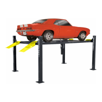
6. Install the post TOP PLATES using the M6 hex bolts,
nuts & washers. Install the nut on each safety ladder un-
til at least 1/2” of threads are exposed and the ladder is
raised at least 1/2” off of the base plate. Be sure to posi-
tion the cable hole INWARD. (See Fig. 3.6 - 3.7)
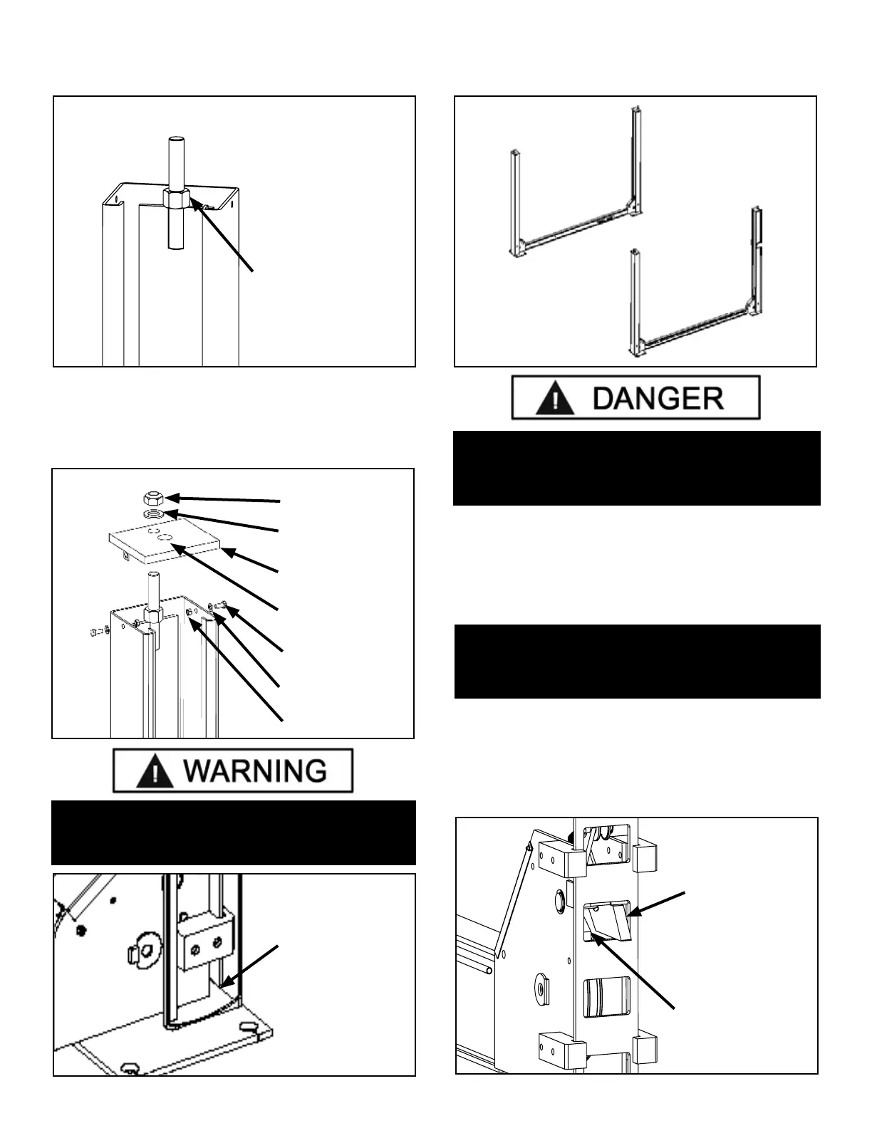
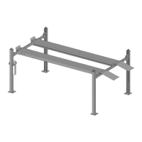
7. The posts and crosstubes are now in position for
ramp installation. (See Fig 3.8)
STEP 4
(Raising The Crosstubes)
1. Crosstubes must be raised off the ground to facilitate
cable routing and ramp assembly.
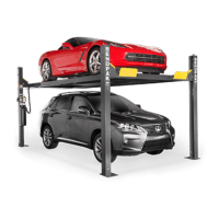
2. Manually raise the Cross Tubes until the Primary
Safety Locks engage and rest on the third or fourth lock
position or approximately 24” o the ground. It is impor-
tant that the SLACK SAFETY LOCK IS DISENGAGED. The
Slack Safety Locks must NEVER rest on the Safety Lad-
ders. (See Fig. 4.1 - 4.4)
Jam Nut must be
installed prior to the
installation of Top
Plate weldment
Fig 3.5
M6 Nut
M6 Washer
M6 Bolt
Top Plate
Weldment
M16 Washer
M16 Nut
Cable Hole
Fig 3.6
Fig 3.7
The Ladder must
never rest on the
base of the column
or damage to the lift
will occur
WARNING!
RAISE THE SAFETY LADDER AT LEAST
1/2” ABOVE THE BASE PLATE OR DAMAGE
TO THE LIFT WILL OCCUR.
Fig 3.8
DANGER!
BE CAREFUL NOT TO DISTURB THE POSTS AND
CROSSTUBES AS THEY MAY TIP OVER CAUSING
PERSONAL INJURY OR HARM.
IMPORTANT NOTE !
IT IS IMPORTANT THAT THE SLACK SAFETY LOCK IS
CLEARED. THE SLACK SAFETY LOCK MUST NEVER
REST ON THE SAFETY LADDER.
Fig 4.1
Primary Safety
Lock Engaged
Slack Safety Lock
Disengaged