25
STEP 13
(Lift Start Up / Final Adjustments)
1. Make sure the Power Unit Reservoir is full with four
(4) gallons of 10-WT hydraulic oil or Dexron-III automatic
transmission fluid.
2. Spray the inside of the posts where the Slide Blocks
glide with a light spray-oil.
3. Test the Power Unit by pressing the push-button
switch on the motor. If the motor sounds like it is operat-
ing properly, raise the lift and check all hose connections
for leaks. If the motor gets hot or sounds peculiar, stop
and check all electrical connections.
4. Before proceeding, make sure all cables are prop-
erly positioned within the grooves of ALL sheaves. Make
sure all Cable Sheave Retaining Clips and or Screws are
secure.
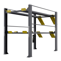
5. Check to make sure that all slack safety locks are
cleared and free. (See Fig. 13.1)
6. Continue pressing the raise button until the cables
are taut and the lift starts to move.
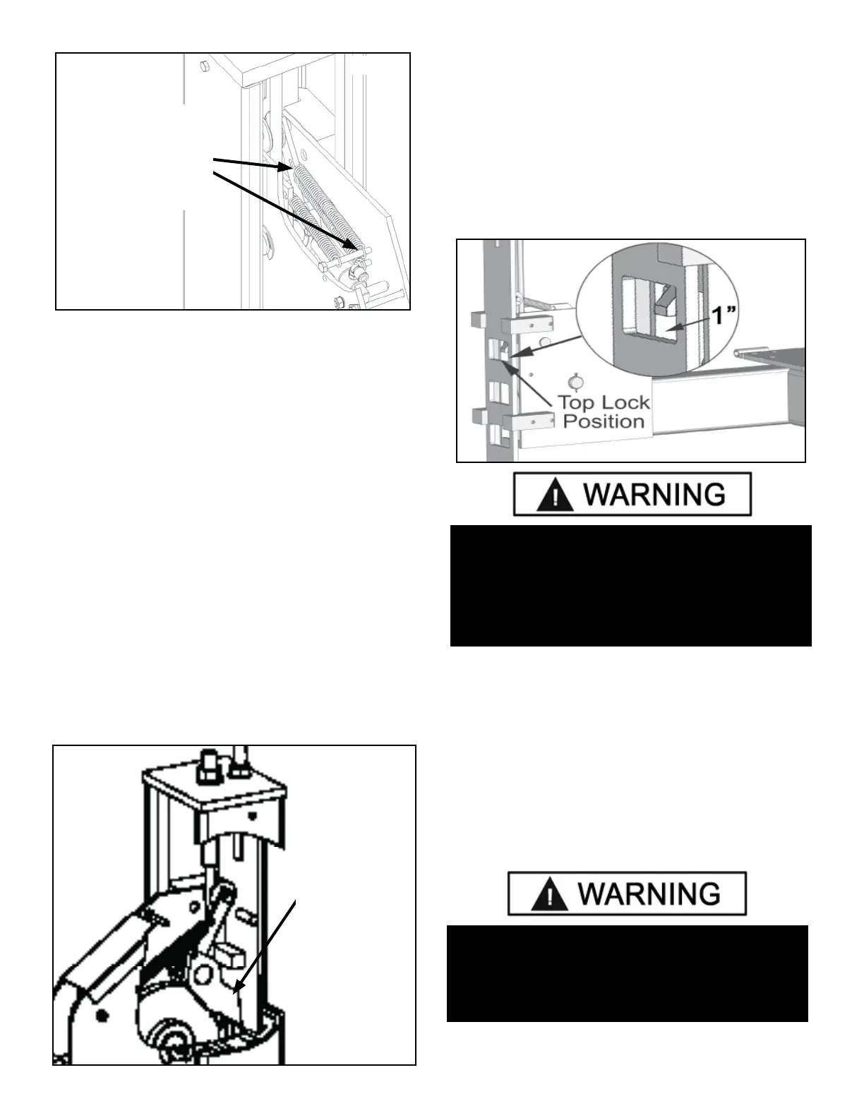
7. RAISE LIFT UNTIL THE CYLINDER BOTTOMS OUT
AND THE LIFT STOPS. ADJUST EACH CABLE SO THAT
EACH SAFETY LOCK RESTS AT ONE INCH ABOVE THE
TOP SAFETY LOCK POSITION. It may be necessary to
tighten or loosen each Cable to reach the proper height.
The Cable Nuts MUST be tightened until there is at least
one inch of threads protruding through the nut. (See Fig.
13.2)
NOTE:
There will be initial stretching of the cables in the
beginning and/or with increased loads. Adjust the
Cables
as outlined above a week after first use, then every
three to six months thereafter depending on usage
and/or to compensate for stretch.
8. After connecting the air supply, press the PUSH
BUTTON AIR VALVE and check that all safety locks are
functioning properly. Lower the lift by pressing the push
button air valve and power unit lowering valve simulta-
neously.
WARNING!
ALL CABLE NUTS MUST BE TIGHTENED ON EACH
END UNTIL THERE IS AT LEAST ONE INCH OF
THREADS PROTRUDING THROUGH THE NUT.
FAILURE TO DO SO COULD RESULT IN SERIOUS
INJURY OR DEATH.
Fig 13.1
Slack safety
should be
positioned as
shown
Fig 12.1
Make sure the ends
of all three (3) springs
are securely attached
to the Safety Locks
and Cross Tube
anchor points.
Fig 13.2
WARNING!
KEEP HANDS AND FEET CLEAR. REMOVE HANDS
AND FEET FROM ANY MOVING PARTS. KEEP FEET
CLEAR OF LIFT WHEN LOWERING. AVOID PINCH
POINTS.