16
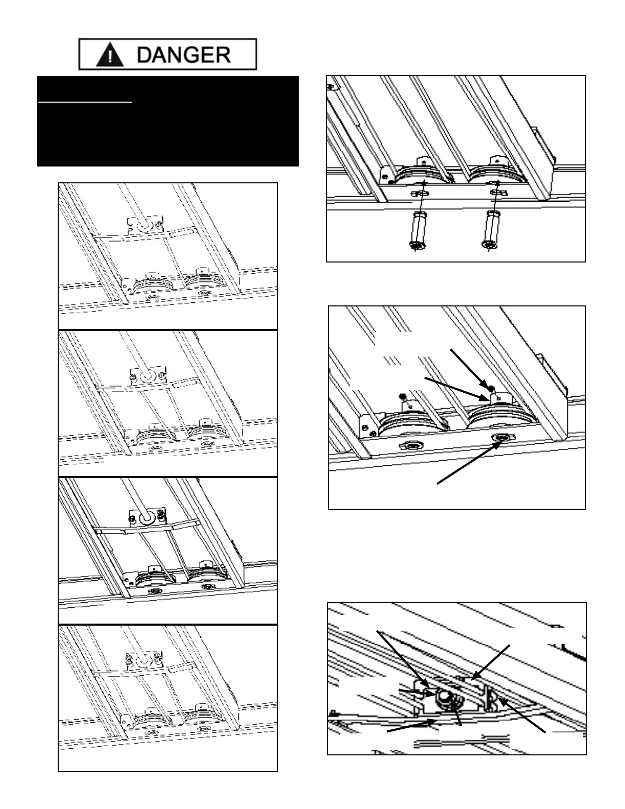
4. With the cables properly routed, hold the sheaves in
position and install the sheave axle. (See Fig. 7.12)
5. Install the Socket Head Cap Screws though the Sheave
Axle Collars. (See Fig. 7.13)
6. Repeat the same procedure at the other end of the lift.
7. Each cable must be installed through the CABLE RETAIN-
ER first to keep the cables stowed in their proper position on the
Cable Block. Install the Cylinder Nut so that it is no more than 1/8”
away from the retaining C-clip. (See Fig. 7.14)
DANGER !
DO NOT PROCEED UNLESS VISUAL CONFIRMATION
IS MADE OF ALL SAFETY LOCKS. ALL LOCKS MUST
BE ENGAGED BEFORE PROCEEDING. FAILURE TO
COMPLY WITH THESE INSTRUCTIONS MAY RESULT
IN SEVERE PERSONAL INJURY OR DEATH.
(SEE PAGE 30)
Cable Routing
Fig 7.11
Fig 7.10
Fig 7.9
Fig 7.8
Cable “A”
Cable “D”
Cable “C”
Cable “B”
Fig 7.12
Socket Head
Cap Screw
Sheave Axle
Fig 7.13
Sheave Axle
Collar
Fig 7.14
Cable Button
Cable Retainer
Cylinder Guide
Cable Block
Cylinder Nut
C-Clip