STEP 3
(Power Unit Set Up)
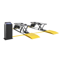
1. Set the Power Unit on the Stand and mount using the
four M8 bolts Nuts and Flat Washers.
(See Fig. 3.1)
2. Fill the reservoir with 6 Quarts / 1.5 gals of Dexron III
ATF or 10W Non-foaming hydraulic fluid.
STEP 4
(Layout)
1. Remember that the lift moves rearward
approximately 14” when raised. (See Fig. 4.1)
2. After selecting a site, place the unit in position
making sure the Hydraulic Cylinder is placed towards the
front of the bay. (Engine should be positioned at Cylinder
side of lift.) (See Fig. 4.2)
3. Select a site for the Power Unit so that operators
have a full, unobstructed view of the lift.
STEP 5
(Connecting Hydraulic Fittings / Hoses)
1. Remove the plastic plug from the left port of the
Cylinder. (See Fig. 5.1)
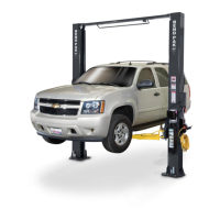
2. Install the Straight Hydraulic Fitting in the left port of
the Cylinder. Use Teflon Tape on the Cylinder side on the
Fitting only. (See Fig. 5.1)
Connect one end of the 143” Hydraulic Hose Assy making
sure to not over-tighten. Do not use Teflon Tape on this
connection.
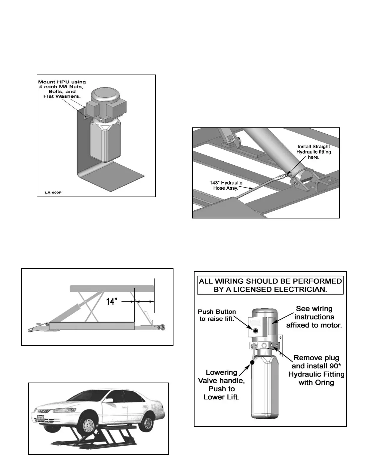
3. Install the 90-degree hydraulic Fitting in the pressure
port of the Power Unit. The pressure port is covered with
a plastic plug. (See Fig 5.2)
4. Connect the 143” Hydraulic Hose to the Power Unit
fitting . Do not use Teflon Tape on this connection, make
sure to not over-tighten.
9
Fig. 3.1
Fig. 4.2
Fig. 5.1
Fig. 4.1
Fig. 5.2