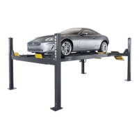
PL-12000DP Series Parking Lift 35 P/N 5900285 — Rev. A1 — February 2023
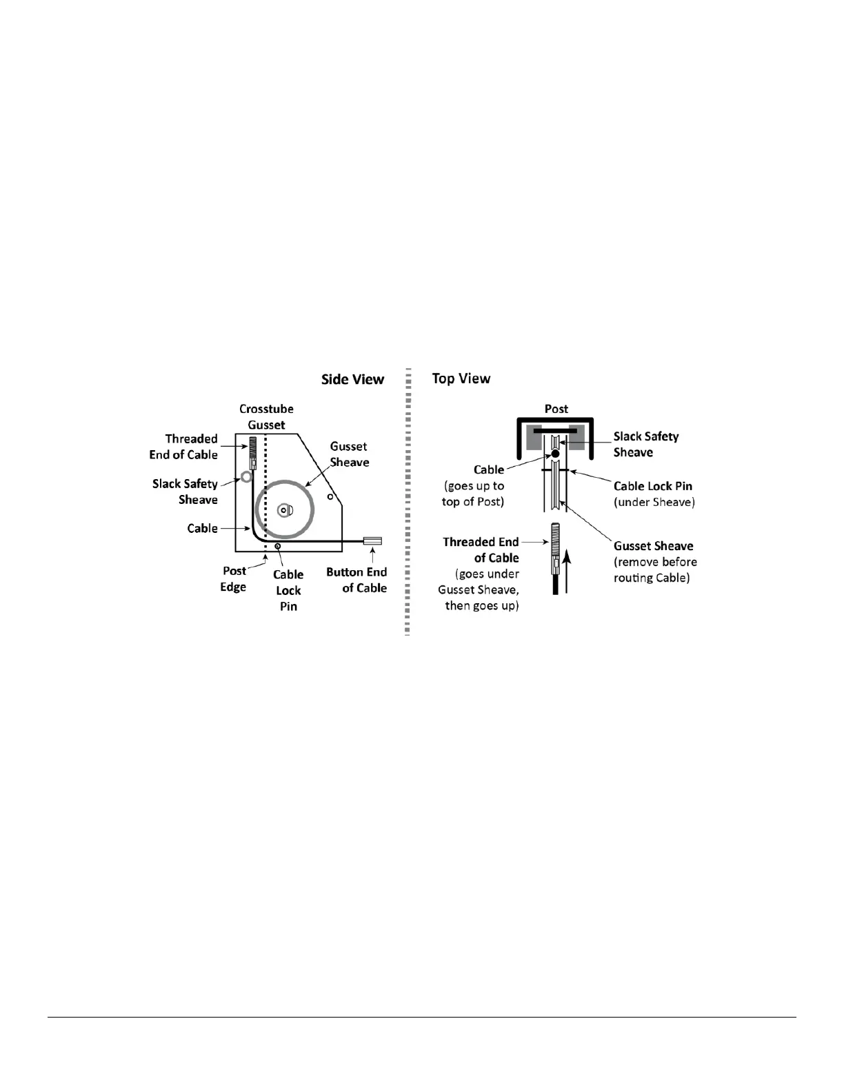
Before routing the Cables, extend the Hydraulic Cylinder’s Piston and Retaining Plate. A suitable
“Come-Along” and/or compressed air applied from an Air Blow Gun into the Hydraulic Cylinder’s
air pressure orifice can be used to assist.
To route Lifting Cables A and C:
1.
Starting with Lifting Cable A
, move the entire cable to just under the Large Window that it
laces through, near the bottom of Post A.
Check the cable’s label to ensure the correct Lifting Cable is selected.
2. Remove the Nut and Washer from the Threaded End (place aside).
3. Route the Threaded End of Lifting Cable A into its Large Window on the Crosstube, push it
towards Post A, and then pull the Threaded End out of the Crosstube at the bottom of the Gusset.
4. Route the Threaded End of Lifting Cable A
under
where the Gusset Sheave will go when it is
reinstalled, then route it up towards the top of the Post past the top of the Crosstube Gusset.
When routing the Cable up, it must lace between the Gusset Sheave and Slack Safety Sheave, as
shown below.
Important: Also note; when routing a Lifting Cable through the Cross Tube (figure below) it must first
lace
under
the Runway Mounting Bolts and behind where the Cross Tube Sheaves will next install
and operate. Then when the Cable (that runs on the Sheave closest to the Post) is routed up towards
the top of the Post, it must run under and up where the Gusset Sheave will be installed, and up to
where the Slack Safety Sheave already is. If Cables are
not routed exactly along these
pathways
, the runway operation and Slack Safeties will
not
function correctly.