3. The red probe connects the black terminal of the stabilizer and the black probe connects white
terminals of the stabilizer (white1, white2, white3). Pointers indicate values. If not, the stabilizer is
damaged and needs replacement.
* Note
• Do not touch any metal part of the
test rod of the multimeter with your
finger for check.
• Check with multimeter. Different
multimeters show different
impedance and different results.
Replace the voltage-current regulator when the impedance between terminals is abnormal.
1.6 Magneto charging coil
* Note
Check the magneto charging coil on
the engine.
Check
Remove the 6p connector of the magneto.
Measure impedance between the white coil of the magneto and the body with
multimeter.
Standard: 0.6-1Ω(68F)
Replace the magneto coil when the measured value exceeds the standard value.
1.7 Magneto disassembly
1.7.1 Disassembly
Remove the body guard.
Fix the flywheel using the universal spanner. Remove
fixing bolts of the flywheel.
Remove the flywheel using the puller tool.
Remove the solid key.
Remove the conductor joint.
Remove the stator.
1.7.2 Installation
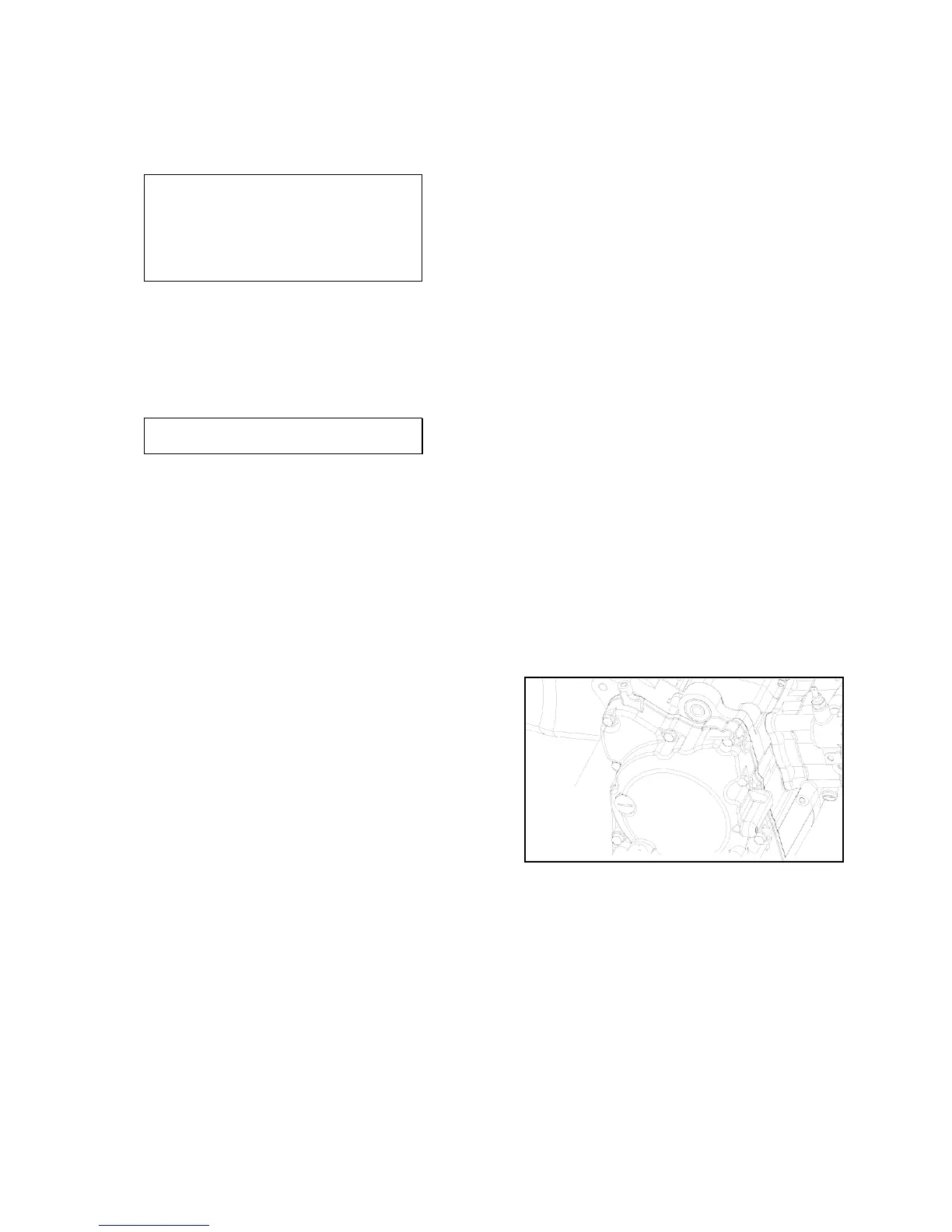
Install the stator on the body of the
engine. Connect the magneto joint.
Clean up the crankshaft and the taper part of the
flywheel. Install the solid key into the groove above the
upper crankshaft key and confirm it.
Aim the groove in the flywheel at the solid key on the
shaft.
* Torque force:9.0 N·m
Install the left body guard.
BOLT