When the maximum voltage measured at the terminal of
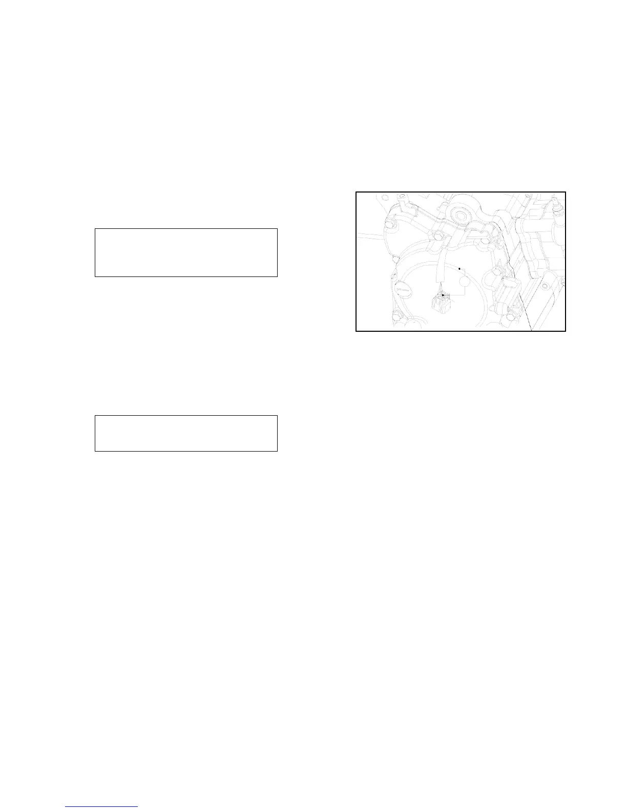
RELATED PARTS Group is abnormal, dismantle the body guard
and the magneto terminal.
Connect the charging coil (black/red) to the shunt. If the voltage of RELATED PARTS is
measured to be abnormal while the voltage at the magneto terminal is normal, it is caused by
poor contact or disconnected wiring.
If the voltage at both RELATED PARTS and magneto terminal
appears to be abnormal, it is caused by poor charging coil. Please
refer to charging coil check.
(B:black R:red W:white G:green BL:blue)
2.3.3 Trigger
* Note
Install the spark plug on the cylinder
head and carry out measurement
when the compression pressure is
normal.
Remove 6P connector of RELATED PARTS group.
Connect the peak-voltage shunt between the trigger with
6P connector (blue/white terminal) and 6P connector
(black terminal).
Press the startup motor or step the actuating lever to
measure the maximum voltage of the trigger.
Connection: positive pole to blue/white; negative pole to
black
Minimum voltage: above 1.7V.
* Note
Never touch any metal part of the test
rod with your finger to avoid electric
shock.
Ω
BL/W
When the maximum voltage measured at the terminal of
RELATED PARTS Group is abnormal, dismantle the right body
guard and the magneto connector. Connect the trigger
(blue/white) to the shunt.
• If the voltage of RELATED PARTS is measured to be abnormal
while the voltage at the magneto terminal is normal, it is
caused by poor contact or disconnected wiring.
• If the voltage at both RELATED PARTS and magneto terminal
appears to be abnormal, it is caused by poor trigger. Please refer
to the table of failure diagnosis.



 To Next Page