32
Base-2 Security Panel
ENGLISH
Connections
Connecting Key and Proximity Readers
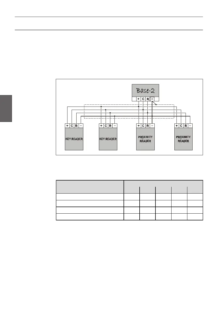
The Base-2 Panel accepts up to 4 command devices (Key Readers and/or
Proximity Readers).
Connect the Readers in parallel through terminals [+], [C], [R] and [–].
Use shielded conductor cable for all connections, with one end of the shield
connected to the Panel Negative, as per the following wiring diagram.
Using the on-board DIP Switches [32], assign a different Address to each of the
connected Readers. Refer to the following table for the 4 available settings.
Example
For Address 03: switch no. 4 must be ON and switches 1, 2, 3 and 5 must be
OFF.
This operation is unnecessary when only one Reader is connected to the Base-2.
Addressing Readers
ADDRESS
DIP SWITCH STRIP [32]
1 2 3 4 5
01 OFF OFF OFF OFF OFF
02 OFF OFF OFF OFF ON
03 OFF OFF OFF ON OFF
04 OFF OFF OFF ON ON