33
Base-2 Security Panel
ENGLISH
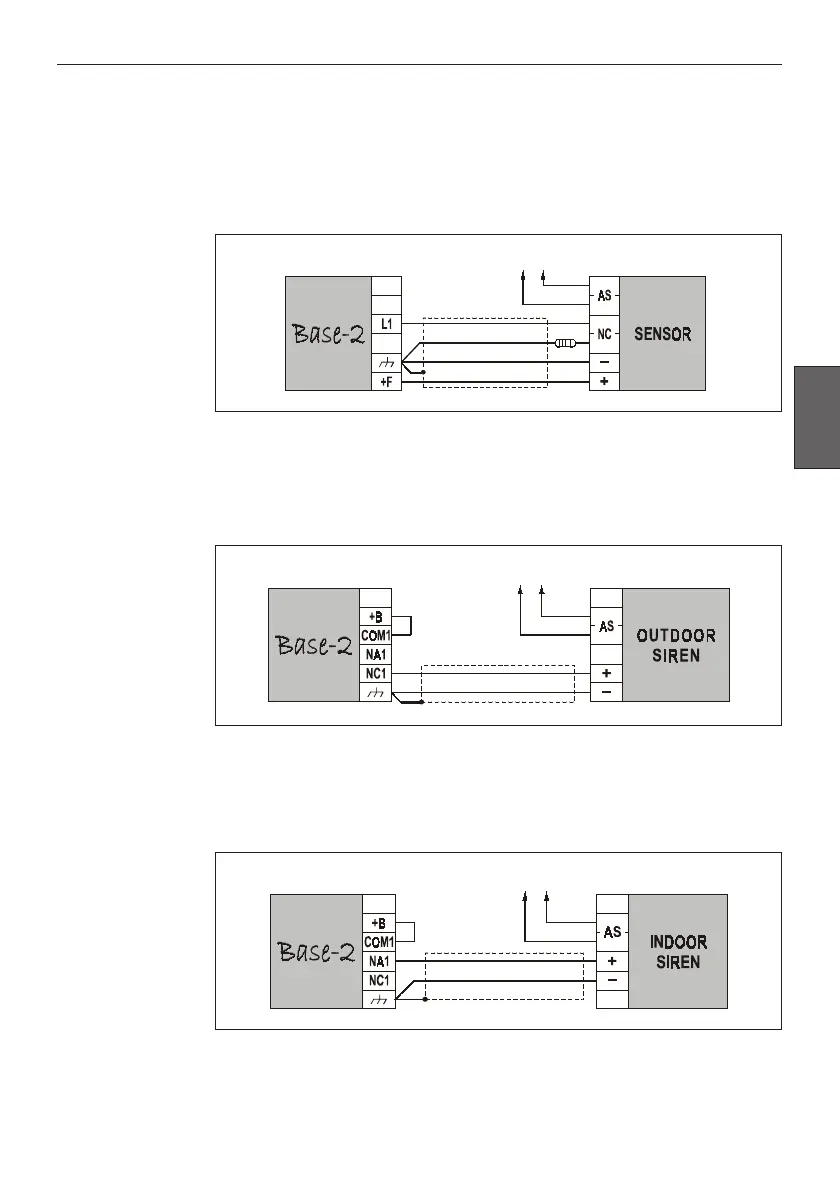
Connecting Sensors
Connect the Sensors to Input Line terminals [L1] and [L2]. The wiring depends
on the setting of switch no.4 of the DIP Switch strip [12], refer to the
“PROGRAMMING” section for details. The following wiring diagram
illustrates the connection of a Sensor to a BALANCED 10K Line. If the Input is
programmed as NC, the 10KΩ-¼ resistor will not be necessary.
Connecting Outdoor Sirens
Connect the Alarm Siren to the free-voltage changeover terminals [NC1], [NA1]
and [COM1]. The following wiring diagram illustrates the connection of a Self-
powered Siren that will activate when the Positive signal fails on terminal [+].
Connecting Indoors Sirens
Connect the Indoor Siren to free-voltage changeover terminals [NC2], [NA2] and
[COM2]. The following wiring diagram illustrates the connection of an Indoor
Siren that will activate when the Positive signal is received on terminal [+].
To Tamper line
10K
To Tamper Line
To Tamper Line