34
Base-2 Security Panel
ENGLISH
EOL Resistor
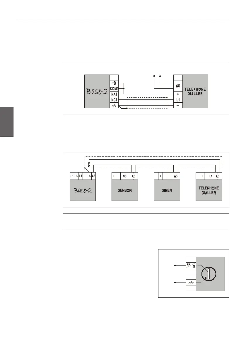
Connecting a Telephone Dialler
The Dialler can be connected to terminals [NC1], [NA1] and [COM1], or
terminals [NC2], [NA2], [COM2], as required. The following wiring diagram
illustrates the connection of a Dialler that will receive a Positive signal on Line L1
during standby status, and will activate when the Positive signal fails.
Connecting the Tamper Line
Connect the tamper wires of peripheral device in series to terminals [AS] and
[
MM
MM
M] of the 24h Balanced 10K Tamper Line, as per the following wiring diagram.
If the 24h Line is not utilized, terminal [AS] must be short-circuited to Nega-
tive by means of a 10K
ΩΩ
ΩΩ
Ω
-¼W resistor.
Connecting Other Devices
The Panel provides 2 Open-Collector
Outputs marked “PR” and “G”. The “PR”
Output will be activated by the Alarm Delay
(Entry Time), and the “G”. Output by
Trouble events. These terminals must be
connected to Negative, as illustrated in the
wiring diagram.
To Tamper Line
10K
To d e v i c e s