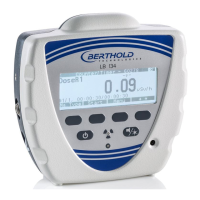
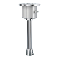
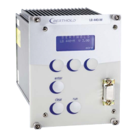
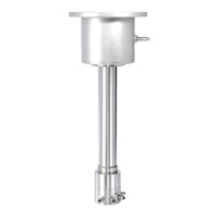
Uni-Probe LB 491
Berthold Technologies GmbH & Co. KG
1 – 89
Volume 1 5 Repair, Maintenance and Service
1
5.5 Replacing the Complete Uni-Probe
Write down all software parameters of the installed Uni-Probe.
Disconnect Uni-Probe from power.
Disconnect possibly connected relay contacts and all in- and
outputs from power.
Unscrew housing cover.
Open wiring on digital board and on the terminal clamps.
If the wires are not marked, we recommend marking the individual
wires before disconnecting them.
After you have disconnected the wires and cables, replace the
housing cover immediately to protect the thread during dismount-
ing of the device.
Dismantle Uni-Probe from fixture.
Mount new Uni-Probe on fixture.
Unscrew housing cover of new Uni-Probe.
Connect wires.
Close the housing carefully with the cover. Attach the cover
carefully onto the housing and tighten it using a torque of
25Nm (standard value).
Before closing, make sure that the threads are clean and greased
with OKS 217.
Turn on po wer.
Enter Uni-Probe parameters which you wrote down, with the
exception of the parameter HV-Default, via the HART
®
Com-
municator or via SIMATIC PDM (see the respective software
description).
Carry out a new empty calibration (see the respective software
description).
Then the Uni-Probe is again ready for use.


 To Next Page