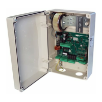
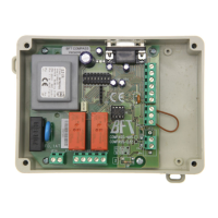
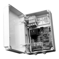
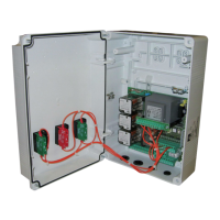
Control unit
EN
- 20 -
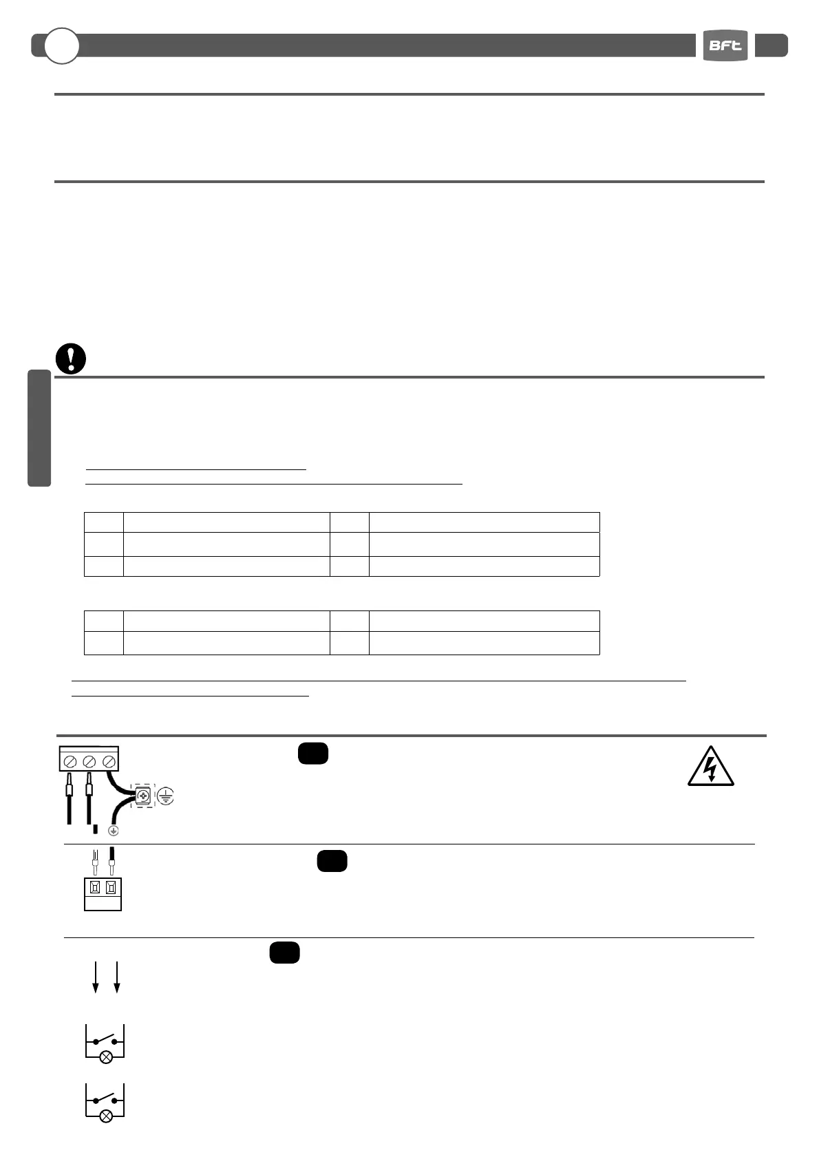
6.3
J5
OUTPUTS/ACCESSORIES POWER SUPPLY
6.1
J1
CONTROL UNIT POWER SUPPLY
In order to reach the level of safety required by current regulations, follow these prescriptions carefully.
1) Make all connections in the terminal block after carefully reading the instructions given in this manual and observing the general
rules and technical standards concerning electrical systems installations.
2) Always t an omnipolar circuit breaker with a contact gap of at least 3 mm.
3) Install a di erential circuit breaker with a threshold of 30 mA.
4) Check the e ectiveness of the protective earth and connect to it all the parts of the automation tted with a terminal or grounding
cable.
5) Fit at least one external warning device, such as a tra c light or ashing light, along with a warning or danger sign.
6) Fit all the safety devices required by the type of installation, taking into consideration the risks it on cause.
7) Separate keep power lines (1.5 mm
2
min. section) from the low-voltage signal lines (0.5 mm
2
min. section).
230Vac 50/60Hz power supply.
Connect LINE and NEUTRAL wires as shown on the board. Use cable type H07RN-F 2x1.5+E min.
Connect the yellow/green EARTH wire of the power supply mains to the earth terminal of the appliance.
6. INPUT AND OUTPUT FUNCTIONALITY AND CONNECTIONS
OUT24
Output 24Vac, 1A max
OUT2
Programmable dry relay output, max. 500mA 24 Vac/dc (parameter - level 2)
OUT3
Programmable dry relay output, max. 500mA 24 Vac/dc (parameter - level 2)
OUT2
OUT2
OUT3
OUT3
24 Vac
4. INSTALLATION SAFETY
3. TECHNICAL SPECIFICATIONS
- Power supply:......................................................230Vac ±10%, 50/60Hz (115Vac on request)
-
Flashing light output
:...............................................................................................230Vac; 40W max
- Accessory output:...........................................................................................24Vac; 24W - 1A max
5. PRELIMINARY OPERATIONS
6.2
J4
FLASHING LIGHT OUTPUT
OUT
LAMP
Output 230Vac, 40W max.
LN
Barriers with standard booms are automatically selected. For special booms (barrier 35 only), before operating the automation,
make sure to have correctly selected the barrier/boom type as follows:
- Press and hold down buttons F and + for 5 seconds.
- Select the barrier/boom type using buttons +/-.
- Press together F and + to con rm.
- Select the actual barrier/boom being used.
Are presented the following choices, depending on the type of INVERTER:
MAXIMA ULTRA 35 / MAXIMA ULTRA 68
MAXIMA ULTRA 36
The Company is not liable for injury to people or animals or damage of things in case of wrong selection of the barrier.
Selecting wrong barrier/boom void warranty.
MAXIMA ULTRA 68
(auto select)
B
oom
ATM 90° (ULTRA 35 only)
MAXIMA ULTRA 35
(auto select)
B
oom
ATM 180° (ULTRA 35 only)
B
oom
Carbon (ULTRA 35 only)
MAXIMA ULTRA 36
(auto select)
B
oom
ARTICULATED
B
oom
Carbon
Xtreme DD4 (fail safe)
ENGLISH