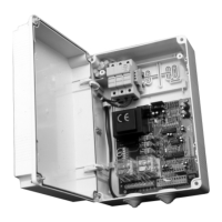
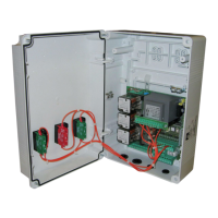
Control unit
EN
- 29 -
The following table gives the 4th level functions and the single parameters.
= DEFAULT value set in factory.
= parameter value set during installation: must be indicated
if DEFAULT value is modi ed.
9.5
4TH
LEVEL PROGRAMMING
Par Function Settable data
Communication protocol
(see notes after the table)
: disabled
: U-LINK
: Modbus/RTU
Setting
U-LINK mode
: Slave
: Master
: Slave for opposing barriers
: Master for opposing barriers
Setting U-LINK adress
Setting Modbus/RTU ID
: For Master
: For Slave
Setting MODBUS RTU speed
: 19 200 baud
: 38 400 baud
Operation counter
Operation counter. Read-only parameter, expressed in hundreds of
operations.
Error History
(see notes after the table)
xx: error list and occurrence alternatively shown
(see chapter 14 “ERROR HANDLING”)
: no history clear
: history is clear
NOTES:
· :
Setting communication protocol. Set value always same to Master and Slave.
·
:
The error list and the occurrence are alternatively shown .
Such as:
<------->
alternating
In the absence of errors or diagnostic events the colors on the cap are xed.
In the presence of error conditions or diagnostic events, ONLY with the stop bar there are ashes with color relating to the error code shown
in the table.
Contact PDM Parameter Pd Cap color
Open 0 Green
Close 0 Red
Open 1 Red
Close 1 Green
COLOR ERROR/EVENT
VIOLET Fuse F3 or F4 burned / stopped active / active fracture input
ORANGE Intervention of the reverser with reopening / number of anomalous encoder pulses
YELLOW Timeout in opening or closing / limit switch both active
LIGHT BLUE Reached the number of cycles scheduled for maintenance
BLUE Lack of communication with the inverter
WHITE Other error
· : Swinging boom sensor input N.C.
swingin boom sensor not mounted or disabled
automation stops immediately in case of swinging boom opened
10. CAP LIGHTS MAXIMA ULTRA 36
On the MAXIMA ULTRA 36 barrier, it is possible to associate a color to the cap when the bar is open and another for all other cases (see para-
meters CO / CC 1st level programming). In the semaphore function, which can be set with Fp = 2, it is possible to link the color (red / green)
to the PDM signal status, regardless of the status of the boom.
ENGLISH