4-4 BL-E30-0515 - 03-01-2018
4-2. CONTROLLER TROUBLESHOOTING
4-2.1. Fault Detection.
The controller provides diagnostics information to
assist technicians in troubleshooting drive system
problems. When a fault is detected, the appropriate
fault code is signaled via the panel mounted LED.
4-2.2. Hand Held Programmer (Optional)
The hand held programmer is available that is
designed specifically for use with the controller. The
programmer is available through your Big Lift LLC
dealer.
4-2.3. Fault Recording.
Fault events are recorded in the controller's memory.
However, multiple occurrences of the same fault are
recorded as one occurrence.
The fault event list can be loaded into the programmer
for readout. The Special Diagnostics mode provides
access to the controller's diagnostic history file. The
history file contains the entire fault event list created
since the diagnostic history file was last cleared. The
standard Diagnostics mode provides information about
only the currently active faults.
4-2.4. General Checkout.
Carefully complete the following checkout procedure.
If you find a problem during the checkout, refer to
paragraph 4-2.7. for further information.
The checkout can be conducted with or without the
handheld programmer (See Paragraph 4-2.2.). How-
ever, the checkout procedure is easier with a program-
mer. To evaluate the system without a programmer,
observe the LED and note the flashing pattern and
refer to Table 4-3 for the code description.
CAUTION: Put the vehicle up on blocks to get the
drive wheel off the ground before begin-
ning these tests.
Turn the keyswitch off and make sure the
brake is applied, the throttle is in neutral,
and the forward/reverse switches are
open.
Do not stand, or allow anyone else to
stand directly in front of or behind the
vehicle during the tests.
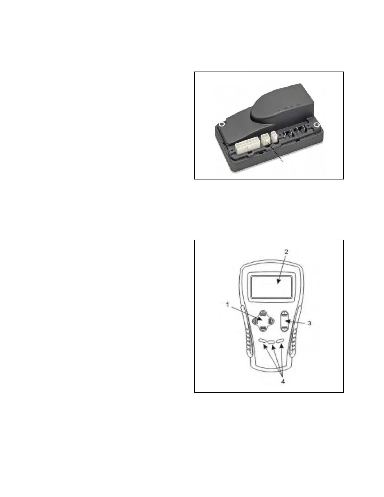
1. Disconnect the battery charger and connect the
programmer to the 4-pin connector (Figure 4-1)
on the controller.
Figure 4-1. Controller Terminals
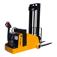
2. Turn the lift truck key switch to the ON position.
The programmer should “power up” with an initial
display (2, Figure 4-2), and the controllers Status
LED should begin steadily blinking a single flash.
If neither happens, check for continuity in the key
switch circuit and controller ground.
Figure 4-2. Hand Held Programmer